Page 1 of 10

PR-1
PROPELLER SHAFT
D DRIVELINE/AXLE
CONTENTS
C
E
F
G
H
I
J
K
L
M
SECTION PR
A
B
PR
Revision: 2006 November2007 350Z
PROPELLER SHAFT
PRECAUTIONS .......................................................... 2
Precautions for Propeller Shaft ................................ 2
PREPARATION ........................................................... 3
Special Service Tools ............................................... 3
NOISE, VIBRATION AND HARSHNESS (NVH)
TROUBLESHOOTING ................................................ 4
NVH Troubleshooting Chart ..................................... 4
REAR PROPELLER SHAFT ...................................... 5
On-Vehicle Inspection .............................................. 5
APPEARANCE AND NOISE INSPECTION .......... 5PROPELLER SHAFT VIBRATION ........................ 5
Components ............................................................. 6
Removal and Installation .......................................... 6
REMOVAL ............................................................. 6
INSPECTION ........................................................ 7
INSTALLATION ..................................................... 8
SERVICE DATA AND SPECIFICATIONS (SDS) ...... 10
General Specifications ............................................ 10
Propeller Shaft Runout Limit ................................... 10
Page 2 of 10
PR-2
PRECAUTIONS
Revision: 2006 November2007 350Z
PRECAUTIONSPFP:00001
Precautions for Propeller ShaftNDS00001
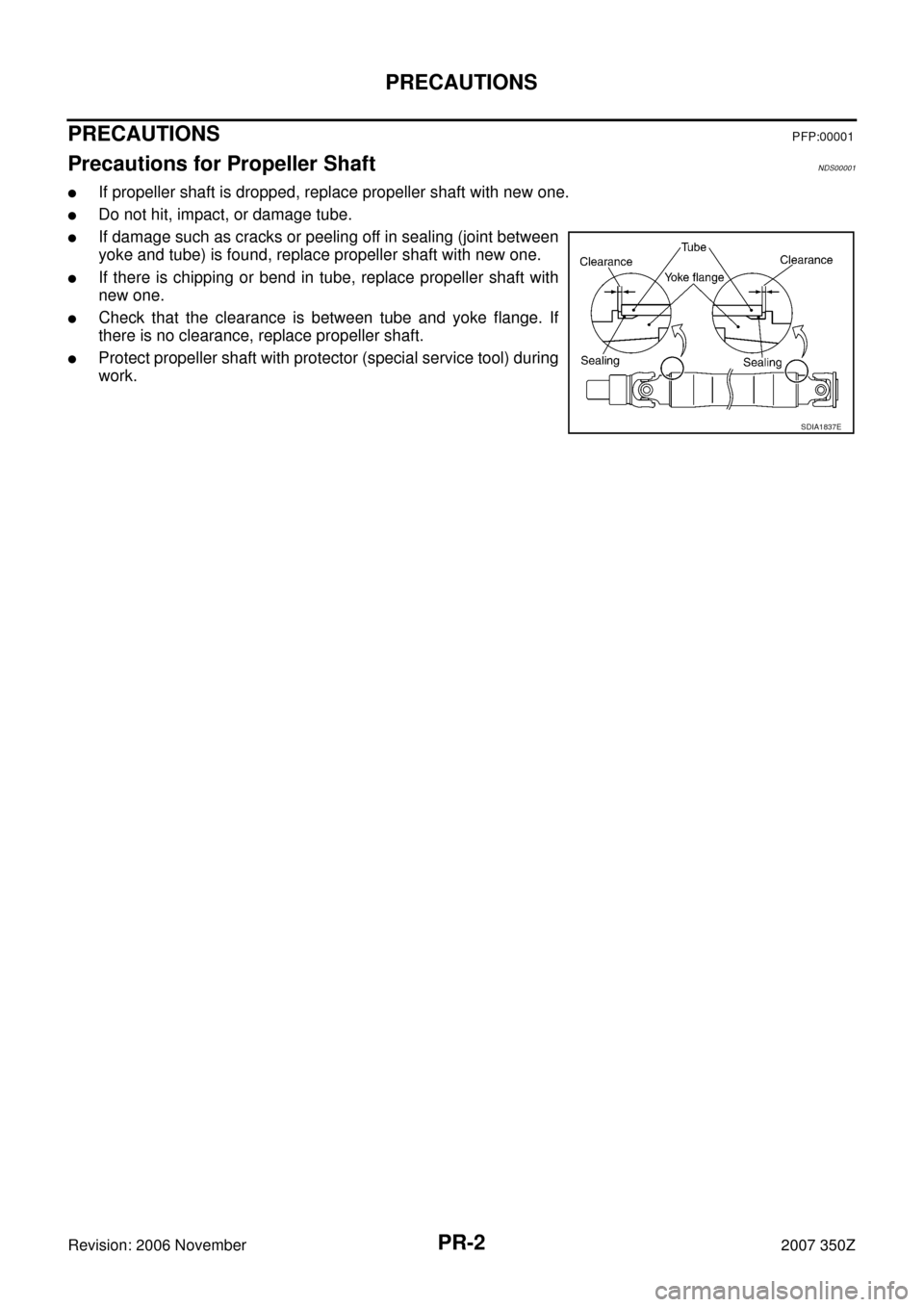
�If propeller shaft is dropped, replace propeller shaft with new one.
�Do not hit, impact, or damage tube.
�If damage such as cracks or peeling off in sealing (joint between
yoke and tube) is found, replace propeller shaft with new one.
�If there is chipping or bend in tube, replace propeller shaft with
new one.
�Check that the clearance is between tube and yoke flange. If
there is no clearance, replace propeller shaft.
�Protect propeller shaft with protector (special service tool) during
work.
SDIA1837E
Page 3 of 10
PREPARATION
PR-3
C
E
F
G
H
I
J
K
L
MA
B
PR
Revision: 2006 November2007 350Z
PREPARATIONPFP:00002
Special Service ToolsNDS00002
The actual shapes of Kent-Moore tools may differ from those of special service tools illustrated here.
Tool number
(Kent-Moore No.)
Tool nameDescription
—
(J-46208)
Propeller shaft protector Removing and installing propeller shaft
SDIA1086E
Page 6 of 10
PR-6
REAR PROPELLER SHAFT
Revision: 2006 November2007 350Z
ComponentsNDS00005
Removal and InstallationNDS00006
REMOVAL
1. Set transmission to neutral position.
2. Release parking brake.
3. To keep space for removing propeller shaft, first detach rear-side
mounts (4 locations) of exhaust tube and main muffler. Then
lower exhaust tube and main muffler, and support them with jack
or equivalent. (See the figure.)
4. Attach protector (special service tool) to propeller shaft. (When
reused.)
1. Propeller shaft
PDIA0645E
PDIA1274E
Tool number : — (J-46208)
SDIA1091E
Page 9 of 10
REAR PROPELLER SHAFT
PR-9
C
E
F
G
H
I
J
K
L
MA
B
PR
Revision: 2006 November2007 350Z
When Installing Reused Propeller Shaft
CAUTION:
When installing propeller shaft, handle it carefully.
1. With protector (special service tool) attached, align matching marks to install propeller shaft to final drive
companion flange, and then tighten to specified torque. Refer to PR-6, "
Components" .
2. Remove protector (special service tool) from propeller shaft.
3. Return exhaust system to its original position. For tightening torque, EX-3, "
EXHAUST SYSTEM" .
4. After assembly, perform a driving test to check propeller shaft vibration. If vibration occurred, separate
propeller shaft from final drive. Reinstall companion flange after rotating it by 90, 180, 270 degrees. Then
perform driving test and check propeller shaft vibration again at each point.
Page 10 of 10
PR-10
SERVICE DATA AND SPECIFICATIONS (SDS)
Revision: 2006 November2007 350Z
SERVICE DATA AND SPECIFICATIONS (SDS)PFP:00030
General SpecificationsNDS00007
Propeller Shaft Runout LimitNDS00008
Applied modelVQ35DE
M/T A/T
Propeller shaft model 2S80A CFRP
Number of joints2
Coupling method with transmission Sleeve type
Type of journal bearings Shell type (Non-disassembly type)
Distance between yokes 95 mm (3.74 in)
Shaft length (Spider to spider) 1321 mm (52.007 in) 1283 mm (50.512 in)
Shaft outer diameter 85.0 mm (3.346 in)
Model2S80A CFRP
Propeller shaft runout limit 1.5 mm (0.059 in) or less


Revision: 2006 November2007 350Z
SERVICE DATA AND SPECIFICATIONS (SDS)PFP:00030
General SpecificationsNDS00007
Propeller Shaft Runout LimitNDS00008
Applied")