Page 23 of 86
IPDM E/R (INTELLIGENT POWER DISTRIBUTION MODULE ENGINE ROOM)
PG-23
C
D
E
F
G
H
I
J
L
MA
B
PG
Revision: 2006 November2007 350Z
IPDM E/R Terminal ArrangementNKS0054C
CKIT0850E
Page 24 of 86

PG-24
IPDM E/R (INTELLIGENT POWER DISTRIBUTION MODULE ENGINE ROOM)
Revision: 2006 November2007 350Z
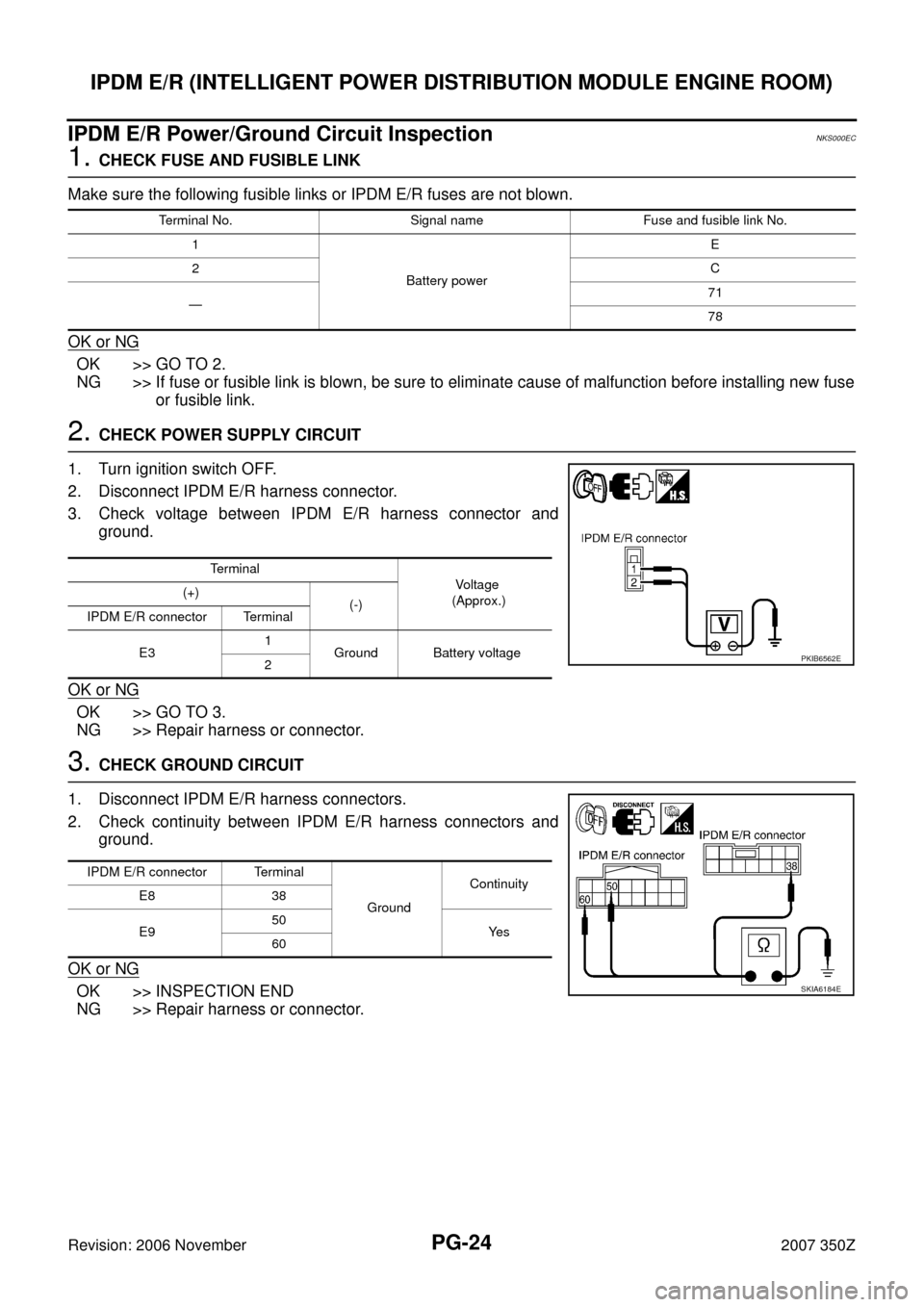
IPDM E/R Power/Ground Circuit InspectionNKS000EC
1. CHECK FUSE AND FUSIBLE LINK
Make sure the following fusible links or IPDM E/R fuses are not blown.
OK or NG
OK >> GO TO 2.
NG >> If fuse or fusible link is blown, be sure to eliminate cause of malfunction before installing new fuse
or fusible link.
2. CHECK POWER SUPPLY CIRCUIT
1. Turn ignition switch OFF.
2. Disconnect IPDM E/R harness connector.
3. Check voltage between IPDM E/R harness connector and
ground.
OK or NG
OK >> GO TO 3.
NG >> Repair harness or connector.
3. CHECK GROUND CIRCUIT
1. Disconnect IPDM E/R harness connectors.
2. Check continuity between IPDM E/R harness connectors and
ground.
OK or NG
OK >> INSPECTION END
NG >> Repair harness or connector.
Terminal No. Signal name Fuse and fusible link No.
1
Battery powerE
2C
—71
78
Terminal
Vo l ta g e
(Approx.) (+)
(-)
IPDM E/R connector Terminal
E31
Ground Battery voltage
2
PKIB6562E
IPDM E/R connector Terminal
GroundContinuity
E8 38
E950
Ye s
60
SKIA6184E
Page 25 of 86
IPDM E/R (INTELLIGENT POWER DISTRIBUTION MODULE ENGINE ROOM)
PG-25
C
D
E
F
G
H
I
J
L
MA
B
PG
Revision: 2006 November2007 350Z
Inspection With CONSULT-III (Self-Diagnosis)NKS000ED
1. CHECK SELF DIAGNOSTIC RESULT
NOTE:
The details for display of the period are as follows:
�CRNT: Error currently detected with IPDM E/R.
�PAST: Error detected in the past and memorized with IPDM E/R.
Contents displayed
NO DTC IS DETECTED.FURTHER TESTING MAY BE REQUIRED.>>INSPECTION END
CAN COMM CIRC>>After print-out of the monitor items, refer to LAN-49, "
CAN Communication Signal
Chart" .
CONSULT-III displayCONSULT-III
display codeTIME
Details of diagnosis result
CRNT PAST
NO DTC IS DETECTED.
FURTHER TESTING MAY BE REQUIRED.— — — No malfunction
CAN COMM CIRC U1000××Any of or several items below have errors.
�TRANSMIT DIAG
�ECM
�BCM
Page 26 of 86
PG-26
IPDM E/R (INTELLIGENT POWER DISTRIBUTION MODULE ENGINE ROOM)
Revision: 2006 November2007 350Z
Removal and Installation of IPDM E/RNKS000EE
REMOVAL
1. Remove battery. Refer to SC-7, "Removal and Installation" .
2. Remove IPDM E/R cover A. While pressing pawl on backside of
IPDM E/R cover B toward vehicle front to unlock, lift up IPDM E/
R.
3. While pressing pawls on right and left side of IPDM E/R, remove
IPDM E/R cover B from IPDM E/R.
4. Remove harness connector from IPDM E/R.
INSTALLATION
Installation is the reverse order of removal.
SKIA4968E
SKIA1902E
SKIA4969E
Page 29 of 86
GROUND
PG-29
C
D
E
F
G
H
I
J
L
MA
B
PG
Revision: 2006 November2007 350Z
ENGINE ROOM HARNESS
CKIT0867E
Page 32 of 86
PG-32
GROUND
Revision: 2006 November2007 350Z
ENGINE CONTROL HARNESS
CKIT0870E
Page 41 of 86
HARNESS
PG-41
C
D
E
F
G
H
I
J
L
MA
B
PG
Revision: 2006 November2007 350Z
HARNESS PFP:00011
Harness Layout NKS000EG
HOW TO READ HARNESS LAYOUT
The following Harness Layouts use a map style grid to help locate
connectors on the figures:
�Main Harness
�Engine Room Harness (Engine Compartment)
�Engine Control Harness (Engine Compartment)
�Body Harness
To Use the Grid Reference
1. Find the desired connector number on the connector list.
2. Find the grid reference.
3. On the figure, find the crossing of the grid reference letter column and number row.
4. Find the connector number in the crossing zone.
5. Follow the line (if used) to the connector.
CONNECTOR SYMBOL
Main symbols of connector (in Harness Layout) are indicated in the below.
SEL252V
CKIT0108E
Page 46 of 86
PG-46
HARNESS
Revision: 2006 November2007 350Z
ENGINE ROOM HARNESS
Engine Compartment
TKIT0890E