Page 1 of 86

PG-1
POWER SUPPLY, GROUND & CIRCUIT ELEMENTS
K ELECTRICAL
CONTENTS
C
D
E
F
G
H
I
J
L
M
SECTION PG
A
B
PG
Revision: 2006 November2007 350Z
POWER SUPPLY, GROUND & CIRCUIT ELEMENTS
PRECAUTIONS .......................................................... 3
Precautions for Battery Service ................................ 3
POWER SUPPLY ROUTING CIRCUIT ...................... 4
Schematic ................................................................ 4
Wiring Diagram — POWER — ................................. 5
BATTERY POWER SUPPLY — IGNITION SW.
IN ANY POSITION ................................................ 5
ACCESSORY POWER SUPPLY — IGNITION
SW. IN “ACC” OR “ON” ....................................... 10
IGNITION POWER SUPPLY — IGNITION SW.
IN “ON” AND/OR “START” ................................... 11
Fuse ....................................................................... 15
Fusible Link ............................................................ 15
Circuit Breaker ....................................................... 15
IPDM E/R (INTELLIGENT POWER DISTRIBUTION
MODULE ENGINE ROOM) ...................................... 16
System Description ................................................ 16
SYSTEMS CONTROLLED BY IPDM E/R ........... 16
CAN COMMUNICATION LINE CONTROL ......... 16
IPDM E/R STATUS CONTROL ........................... 17
CAN Communication System Description .............. 17
CAN Communication Unit ...................................... 17
Function of Detecting Ignition Relay Malfunction ... 17
CONSULT-III Function (IPDM E/R) ........................ 18
SELF-DIAG RESULTS ........................................ 18
DATA MONITOR ................................................. 18
ACTIVE TEST ..................................................... 19
Auto Active Test ..................................................... 20
DESCRIPTION .................................................... 20
OPERATION PROCEDURE ............................... 20
INSPECTION IN AUTO ACTIVE TEST MODE ... 20
Schematic .............................................................. 22
IPDM E/R Terminal Arrangement ........................... 23
IPDM E/R Power/Ground Circuit Inspection .......... 24
Inspection With CONSULT-III (Self-Diagnosis) ...... 25
Removal and Installation of IPDM E/R ................... 26
REMOVAL ........................................................... 26
INSTALLATION ................................................... 26GROUND ................................................................... 27
Ground Distribution ................................................. 27
MAIN HARNESS ................................................. 27
ENGINE ROOM HARNESS ................................ 29
ENGINE CONTROL HARNESS .......................... 32
BODY HARNESS ................................................ 34
BODY NO. 2 HARNESS ..................................... 37
TAIL HARNESS ................................................... 38
BACK DOOR HARNESS .................................... 40
HARNESS ................................................................. 41
Harness Layout ...................................................... 41
HOW TO READ HARNESS LAYOUT ................. 41
OUTLINE ............................................................. 42
MAIN HARNESS ................................................. 43
ENGINE ROOM HARNESS ................................ 46
ENGINE CONTROL HARNESS .......................... 50
BODY HARNESS ................................................ 53
BODY NO. 2 HARNESS ..................................... 58
TAIL HARNESS ................................................... 59
TAIL NO. 2 HARNESS ........................................ 62
ROOM LAMP HARNESS .................................... 63
DOOR HARNESS ............................................... 65
Wiring Diagram Codes (Cell Codes) ...................... 67
ELECTRICAL UNITS LOCATION ............................ 70
Electrical Units Location ......................................... 70
ENGINE COMPARTMENT .................................. 70
PASSENGER COMPARTMENT ......................... 71
LUGGAGE COMPARTMENT .............................. 74
HARNESS CONNECTOR ......................................... 76
Description .............................................................. 76
HARNESS CONNECTOR (TAB-LOCKING
TYPE) .................................................................. 76
HARNESS CONNECTOR (SLIDE-LOCKING
TYPE) .................................................................. 77
HARNESS CONNECTOR (LEVER LOCKING
TYPE) .................................................................. 78
ELECTRICAL UNITS ................................................ 79
Terminal Arrangement ............................................ 79
SMJ (SUPER MULTIPLE JUNCTION) ..................... 81
Terminal Arrangement ............................................ 81
Page 3 of 86
PRECAUTIONS
PG-3
C
D
E
F
G
H
I
J
L
MA
B
PG
Revision: 2006 November2007 350Z
PRECAUTIONSPFP:00001
Precautions for Battery ServiceNKS0054E
Before disconnecting the battery, lower both the driver and passenger windows. This will prevent any interfer-
ence between the window edge and the vehicle when the door is opened/closed. During normal operation, the
window slightly raises and lowers automatically to prevent any window to vehicle interference. The automatic
window function will not work with the battery disconnected.
Page 5 of 86
POWER SUPPLY ROUTING CIRCUIT
PG-5
C
D
E
F
G
H
I
J
L
MA
B
PG
Revision: 2006 November2007 350Z
Wiring Diagram — POWER —NKS004SY
BATTERY POWER SUPPLY — IGNITION SW. IN ANY POSITION
TKWT5813E
Page 24 of 86

PG-24
IPDM E/R (INTELLIGENT POWER DISTRIBUTION MODULE ENGINE ROOM)
Revision: 2006 November2007 350Z
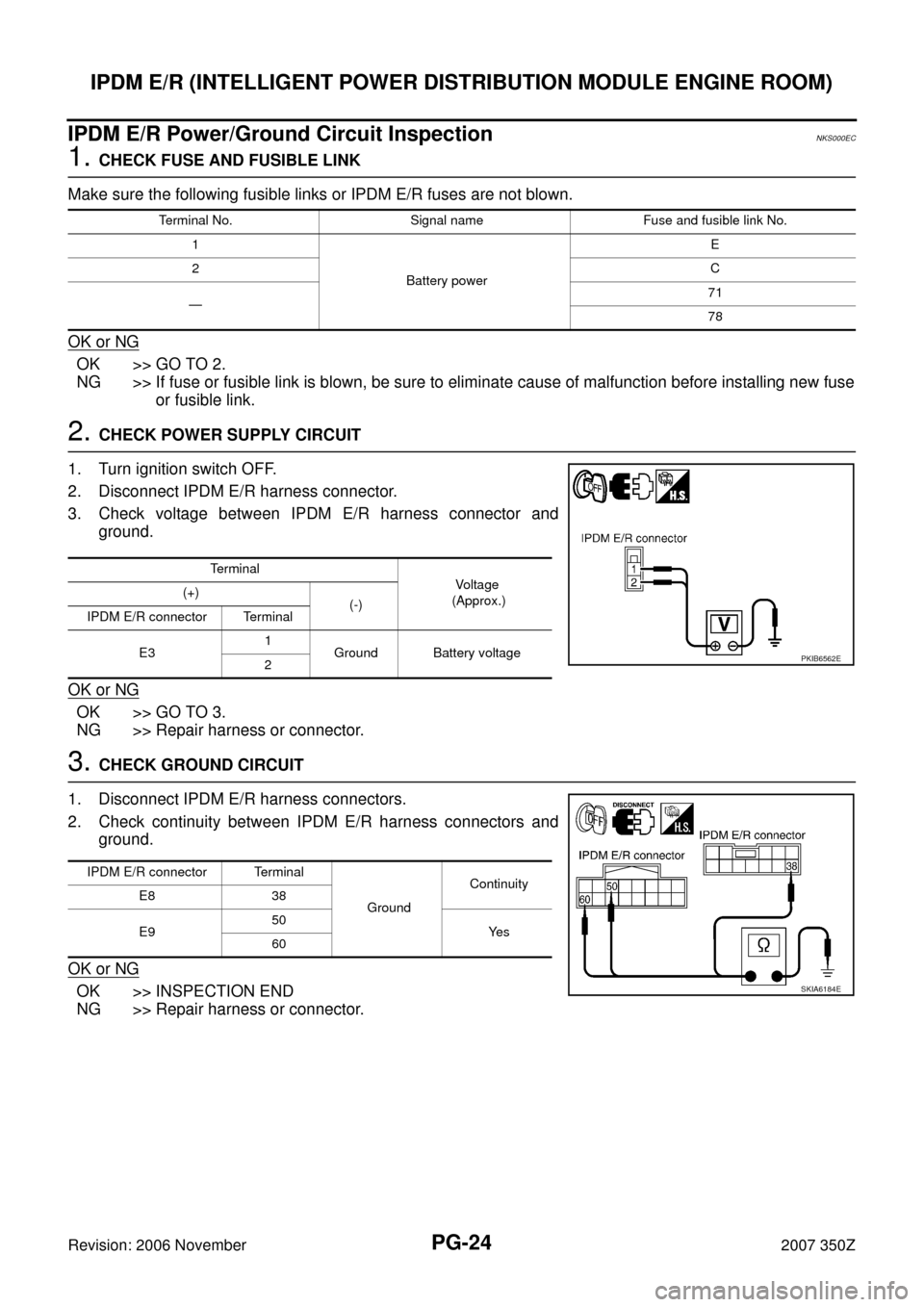
IPDM E/R Power/Ground Circuit InspectionNKS000EC
1. CHECK FUSE AND FUSIBLE LINK
Make sure the following fusible links or IPDM E/R fuses are not blown.
OK or NG
OK >> GO TO 2.
NG >> If fuse or fusible link is blown, be sure to eliminate cause of malfunction before installing new fuse
or fusible link.
2. CHECK POWER SUPPLY CIRCUIT
1. Turn ignition switch OFF.
2. Disconnect IPDM E/R harness connector.
3. Check voltage between IPDM E/R harness connector and
ground.
OK or NG
OK >> GO TO 3.
NG >> Repair harness or connector.
3. CHECK GROUND CIRCUIT
1. Disconnect IPDM E/R harness connectors.
2. Check continuity between IPDM E/R harness connectors and
ground.
OK or NG
OK >> INSPECTION END
NG >> Repair harness or connector.
Terminal No. Signal name Fuse and fusible link No.
1
Battery powerE
2C
—71
78
Terminal
Vo l ta g e
(Approx.) (+)
(-)
IPDM E/R connector Terminal
E31
Ground Battery voltage
2
PKIB6562E
IPDM E/R connector Terminal
GroundContinuity
E8 38
E950
Ye s
60
SKIA6184E
Page 26 of 86
PG-26
IPDM E/R (INTELLIGENT POWER DISTRIBUTION MODULE ENGINE ROOM)
Revision: 2006 November2007 350Z
Removal and Installation of IPDM E/RNKS000EE
REMOVAL
1. Remove battery. Refer to SC-7, "Removal and Installation" .
2. Remove IPDM E/R cover A. While pressing pawl on backside of
IPDM E/R cover B toward vehicle front to unlock, lift up IPDM E/
R.
3. While pressing pawls on right and left side of IPDM E/R, remove
IPDM E/R cover B from IPDM E/R.
4. Remove harness connector from IPDM E/R.
INSTALLATION
Installation is the reverse order of removal.
SKIA4968E
SKIA1902E
SKIA4969E
Page 49 of 86
HARNESS
PG-49
C
D
E
F
G
H
I
J
L
MA
B
PG
Revision: 2006 November2007 350Z
Battery Cable
TKIT0892E