Page 25 of 36

to the thread of adjusting screw to the adjustin")
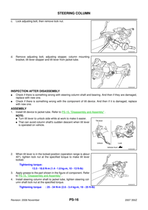
POWER STEERING GEAR
PS-25
C
D
E
F
H
I
J
K
L
MA
B
PS
Revision: 2006 November2007 350Z
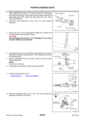
11. Apply thread locking adhesive (Three Bond 1111B or equivalent)
to the thread of adjusting screw to the adjusting screw height
from gear housing assembly. The adjusting screw height is the
same as it was measured in the overhaul in advance.
12. Rotate pinion ten times whole range of rack so that parts get to
fit with each other.
13. Measure pinion rotating torque within from –180° to + 180°
make preload gauge (SST) and torque adapter (SST) in rack
neutral position, then hold preload gauge (SST) at maximum
torque.
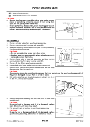
14. After loosening adjusting screw once, tighten it again with torque
of 4.9 - 5.9 N·m (0.50 - 0.60 kg-m, 44 - 52 in-lb). After that
loosen it within from 20° to 40°.
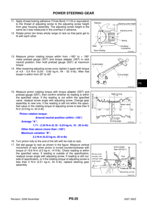
15. Measure pinion rotating torque with torque adapter (SST) and
preload gauge (SST), then confirm whether its reading is within
the specified value. If the reading is not within the specified
value, readjust screw angle with adjusting screw. Change gear
assembly to new one, if the reading is still not within the speci-
fied value or the rotating torque of adjusting screw is less than 5
N·m (0.51kg-m, 44 in-lb)
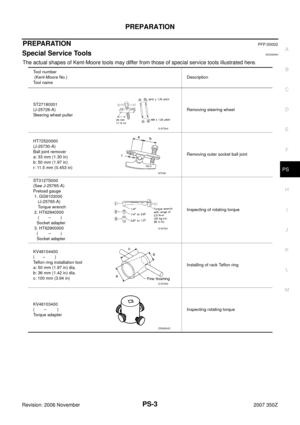
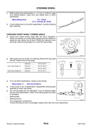
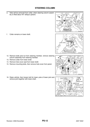
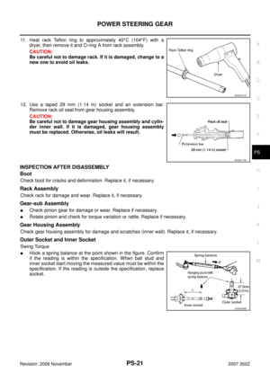
16. Turn pinion fully to the end of the left with tie-rods to rack.
17. Set dial gauge to rack as shown in the figure. Measure vertical
movement of rack when pinion is turned counterclockwise with
torque of 19.6 N·m (2.0 kg-m, 14 ft-lb). Check reading is within
the specified value. If reading is outside of the specification,
readjust screw angle with adjusting screw. If reading is still out-
side of specification, or if the rotating torque of adjusting screw is
less than 5 N·m (0.51 kg-m, 44 in-lb), replace steering gear
assembly.
SGIA0568E
SGIA0159E
Pinion rotation torque:
Around neutral position (within ±100°)
Average “A”:
1.71 - 2.34 N·m (0.18 - 0.23 kg-m, 16 - 20 in-lb)
Other than above (more than ±100°)
Maximum variation “B”:
2.3 N·m (0.23 kg-m, 20 in-lb)
SGIA0160E
SGIA0773E
Page 26 of 36

PS-26
POWER STEERING GEAR
Revision: 2006 November2007 350Z
Specified value
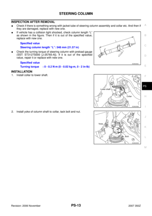
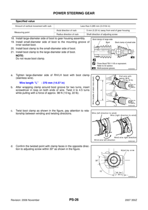
18. Install large-diameter side of boot to gear housing assembly.
19. Install small-diameter side of boot to the mounting groove of
inner socket boot.
20. Install boot clamp to the small-diameter side of boot.
21. Install boot clamp to the large-diameter side of boot.
NOTE:
Do not reuse boot clamp.
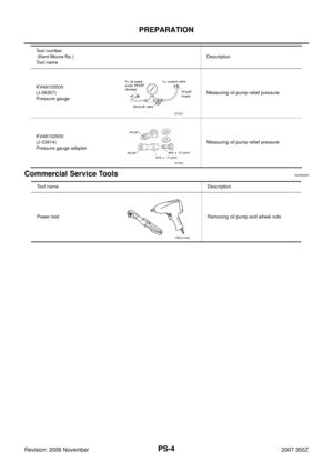
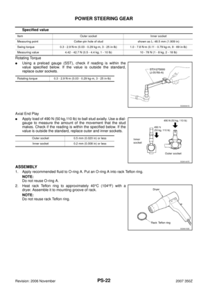
a. Tighten large-diameter side of RH/LH boot with boot clamp
(stainless wire).
b. After wrapping clamp around boot groove for two turns, insert
screwdriver in loop on both ends of wire. Twist 4 to 4.5 turns
while pulling with a force of approx. 98 N (10 kg, 22 lb).
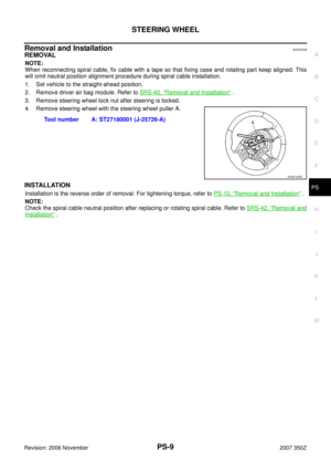
c. Twist boot clamp as shown in the figure, pay attention to rela-
tionship between winding and twisting directions.
d. Confirm the twisted point with clamp faces in the opposite direc-
tion to adjusting screw within 30° as shown in the figure.
Amount of vertical movement with rack Less than 0.265 mm (0.0104 in)
Measuring pointAxial direction of rack 5 mm (0.20 in) away from end of gear housing
Radius direction of rack Shaft direction of adjusting screw
SGIA0550E
Wire length “L” : 370 mm (14.57 in)
SGIA0163E
SGIA0164E
SGIA0361E
Page 27 of 36
POWER STEERING GEAR
PS-27
C
D
E
F
H
I
J
K
L
MA
B
PS
Revision: 2006 November2007 350Z
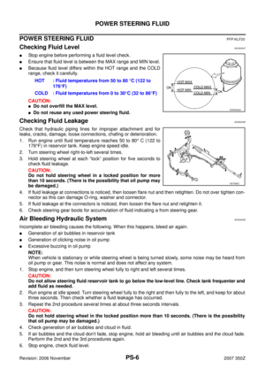
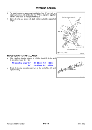
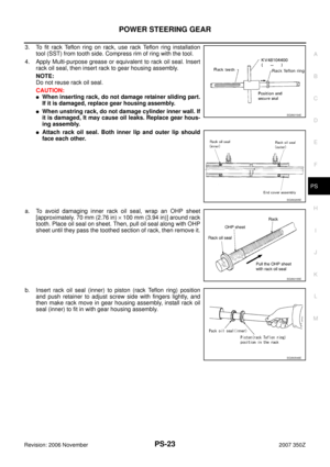
e. After twisting wire 4 to 4.5 turns, bend cut end of wire. Cut end of
wire should not touch boot. Be sure wire end is at least 5 mm
(0.20 in) away from clearance for tube.
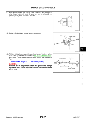
22. Install cylinder tubes to gear housing assembly.
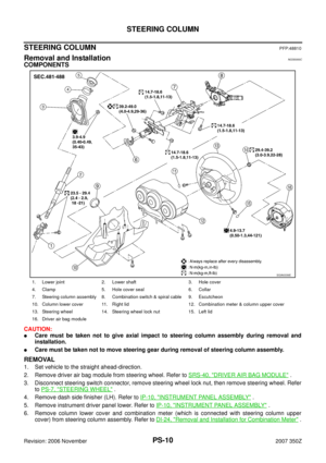
23. Tighten lightly inner socket in specified length “L”, then tighten
lock nut at specified torque. Refer to PS-19, "
COMPONENTS" .
Reconfirm if inner socket length is within limit of specified length
“L”.
CAUTION:
Perform toe-in adjustment after this procedure. Length
achieved after toe-in adjustment is not necessarily value
given here.
SGIA0166E
SGIA0360E
Inner socket length “L” : 106.3 mm (4.19 in)
SGIA0167E
Page 28 of 36

PS-28
POWER STEERING OIL PUMP
Revision: 2006 November2007 350Z
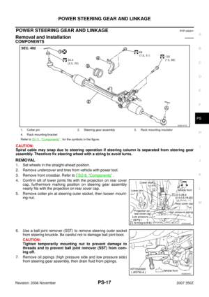
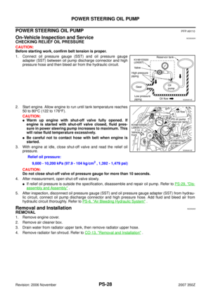
POWER STEERING OIL PUMPPFP:49110
On-Vehicle Inspection and ServiceNGS0000H
CHECKING RELIEF OIL PRESSURE
CAUTION:
Before starting work, confirm belt tension is proper.
1. Connect oil pressure gauge (SST) and oil pressure gauge
adapter (SST) between oil pump discharge connector and high
pressure hose and then bleed air from the hydraulic circuit.
2. Start engine. Allow engine to run until tank temperature reaches
50 to 80°C (122 to 176°F).
CAUTION:
�Warm up engine with shut-off valve fully opened. If
engine is started with shut-off valve closed, fluid pres-
sure in power steering pump increases to maximum. This
will raise fluid temperature excessively.
�Be careful not to contact hose with belt when engine is
started.
3. With engine at idle, close shut-off valve and read the relief oil
pressure.
CAUTION:
Do not close shut-off valve of pressure gauge for more than 10 seconds.
4. After measurement, open shut-off valve slowly.
�If relief oil pressure is outside the specification, disassemble and repair oil pump. Refer to PS-29, "Dis-
assembly and Assembly" .
5. After inspection, disconnect oil pressure gauge (SST) and oil pressure gauge adapter (SST) from hydrau-
lic circuit, connect oil pump discharge connector and high pressure hose. Add fluid and bleed air from
hydraulic circuit thoroughly. Refer to PS-6, "
Air Bleeding Hydraulic System" .
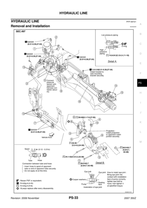
Removal and InstallationNGS0000I
REMOVAL
1. Remove engine cover.
2. Remove air cleaner box.
3. Drain water from radiator upper tank, then remove radiator upper hose.
4. Remove radiator fan shroud. Refer to CO-13, "
Removal and Installation" .
SGIA0814E
Relief oil pressure:
9,600 - 10,200 kPa (97.9 - 104 kg/cm
2 , 1,392 - 1,479 psi)
SGIA0813E
Page 29 of 36

POWER STEERING OIL PUMP
PS-29
C
D
E
F
H
I
J
K
L
MA
B
PS
Revision: 2006 November2007 350Z
5. Loosen idler pulley, then remove belt.
6. Drain power steering fluid from reservoir tank.
7. Remove piping of high pressure and low pressure (drain fluid
from their pipings)
8. Remove bolt common to water pump and power steering pump.
9. Remove bolt then remove power steering pump.
INSTALLATION
Refer to PS-33, "HYDRAULIC LINE" for tightening torque. Install in the reverse order of removal.
�After installation, adjust belt tension. Refer to EM-12, "DRIVE BELTS" .
�After installation, bleed air. Refer to PS-6, "Air Bleeding Hydraulic System" .
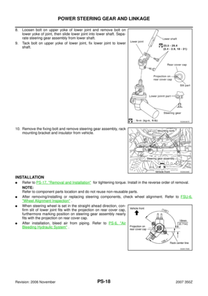
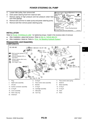
Disassembly and AssemblyNGS0000J
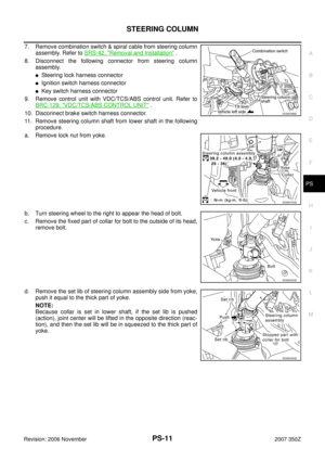
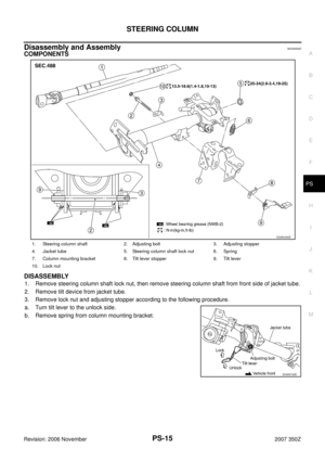
COMPONENTS
SGIA0376E
1. Plug 2. O-ring D 3. Flow control valve spring
4. Relief valve assembly 5. Flow control valve assembly 6. Shaft kit
7. Oil seal 8. Bracket 9. Body assembly
10. Suction connector assembly 11. O-ring E 12. O-ring C
13. O-ring B 14. Cartridge assembly 15. O-ring A
16. Cover assembly 17. Side plate 18. Vane
19. Rotor snap ring 20. Cam ring 21. Rotor
22. Dowel pin
SGIA0774E
Page 30 of 36

PS-30
POWER STEERING OIL PUMP
Revision: 2006 November2007 350Z
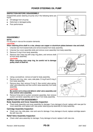
INSPECTION BEFORE DISASSEMBLY
Disassemble power steering oil pump only if the following items are
found.
�Oil leakage from oil pump
�Deformed or damaged pulley
�Poor performance
DISASSEMBLY
NOTE:
Fix oil pump in vise as the occasion demands.
CAUTION:
When retaining drive shaft in a vise, always use copper or aluminium plates between vise and shaft.
1. Unscrew two front bracket bolts and remove bracket from body assembly.
2. Unscrew four cover assembly bolts and remove cover assembly from body assembly.
3. Remove O-ring A from body assembly.
4. Remove rotor snap ring with snap ring pliers, and remove shaft
kit from body assembly.
CAUTION:
When removing rotor snap ring, be careful not to damage
pulley shaft of shaft kit.
5. Using a screwdriver, remove oil seal for body assembly.
6. Remove cam ring, rotor, vane, side plate, O-ring B and O-ring C
from body assembly.
7. Remove plug, then remove O-ring D, flow control valve spring,
relief valve assembly and flow control value assembly from body
assembly.
CAUTION:
Be careful not to drop and deform relief valve assembly and
flow control valve assembly.
8. Remove fixing bolt of suction connector assembly, then remove
suction connector assembly and O-ring E from body assembly.
INSPECTION AFTER DISASSEMBLY
Body Assembly and Cover Assembly Inspection
�Check body assembly and cover assembly for damage. If any damage is found, replace with new part for
cover assembly, and replace with new power steering pump assembly for body assembly.
Cartridge Assembly Inspection
�Check cam ring, side plate, rotor and vane for damage. If any damage is found, replace cartridge assem-
bly with new one.
Relief Valve Assembly Inspection
�Check relief valve assembly for damage. If any damage is found, replace it with new one.
SGIA0170E
SGIA0059E
SST034A
Page 31 of 36

POWER STEERING OIL PUMP
PS-31
C
D
E
F
H
I
J
K
L
MA
B
PS
Revision: 2006 November2007 350Z
Flow Control Valve Assembly Inspection
�Check flow control valve assembly for damage. If any damage is found, replace it with new one.
ASSEMBLY
NOTE:
Fix oil pump in vise as occasion demands.
CAUTION:
When retaining drive shaft in a vise, always use copper or aluminium plates between vise and shaft.
1. Apply a coat of Multi-purpose grease or equivalent to oil seal lip
and to the circumference of oil seal. Using proper tool such as
hand press machine, install it to the body assembly.
NOTE:
Do not reuse oil seal.
2. Install shaft kit to body assembly.
3. Apply recommended fluid to O-ring B and O-ring C, then install
O-ring B and O-ring C to body assembly.
NOTE:
Do not reuse O-ring B and O-ring C.
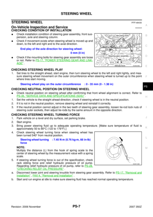
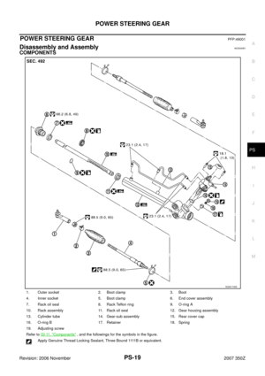
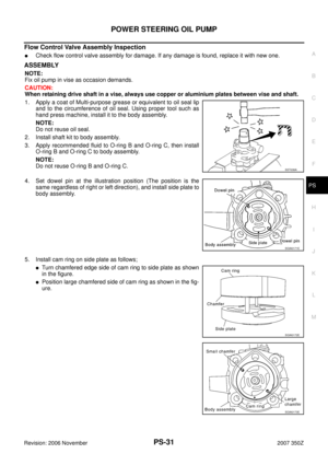
4. Set dowel pin at the illustration position (The position is the
same regardless of right or left direction), and install side plate to
body assembly.
5. Install cam ring on side plate as follows;
�Turn chamfered edge side of cam ring to side plate as shown
in the figure.
�Position large chamfered side of cam ring as shown in the fig-
ure.
SST038A
SGIA0171E
SGIA0172E
SGIA0173E
Page 32 of 36
.
7. Install vane to rotor (vane dir")
PS-32
POWER STEERING OIL PUMP
Revision: 2006 November2007 350Z
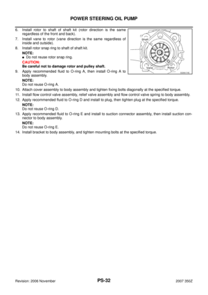
6. Install rotor to shaft of shaft kit (rotor direction is the same
regardless of the front and back).
7. Install vane to rotor (vane direction is the same regardless of
inside and outside).
8. Install rotor snap ring to shaft of shaft kit.
NOTE:
�Do not reuse rotor snap ring.
CAUTION:
Be careful not to damage rotor and pulley shaft.
9. Apply recommended fluid to O-ring A, then install O-ring A to
body assembly.
NOTE:
Do not reuse O-ring A.
10. Attach cover assembly to body assembly and tighten fixing bolts diagonally at the specified torque.
11. Install flow control valve assembly, relief valve assembly and flow control valve spring to body assembly.
12. Apply recommended fluid to O-ring D and install to plug, then tighten plug at the specified torque.
NOTE:
Do not reuse O-ring D.
13. Apply recommended fluid to O-ring E and install to suction connector assembly, then install suction con-
nector to body assembly.
NOTE:
Do not reuse O-ring E.
14. Install bracket to body assembly, and tighten mounting bolts at the specified torque.
SGIA0174E