Page 29 of 36

POWER STEERING OIL PUMP
PS-29
C
D
E
F
H
I
J
K
L
MA
B
PS
Revision: 2006 November2007 350Z
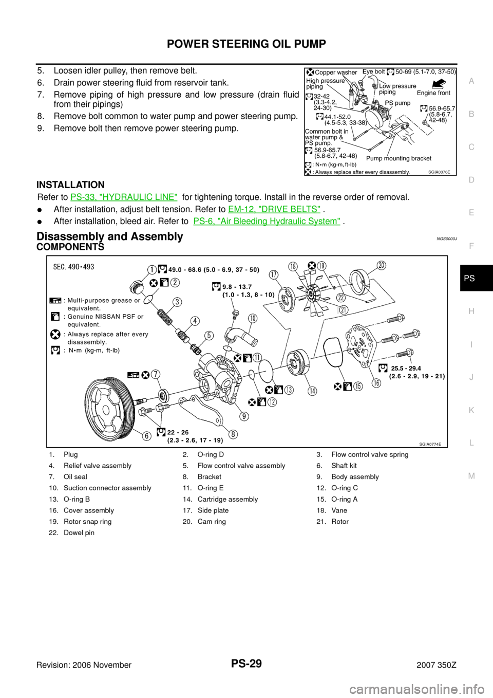
5. Loosen idler pulley, then remove belt.
6. Drain power steering fluid from reservoir tank.
7. Remove piping of high pressure and low pressure (drain fluid
from their pipings)
8. Remove bolt common to water pump and power steering pump.
9. Remove bolt then remove power steering pump.
INSTALLATION
Refer to PS-33, "HYDRAULIC LINE" for tightening torque. Install in the reverse order of removal.
�After installation, adjust belt tension. Refer to EM-12, "DRIVE BELTS" .
�After installation, bleed air. Refer to PS-6, "Air Bleeding Hydraulic System" .
Disassembly and AssemblyNGS0000J
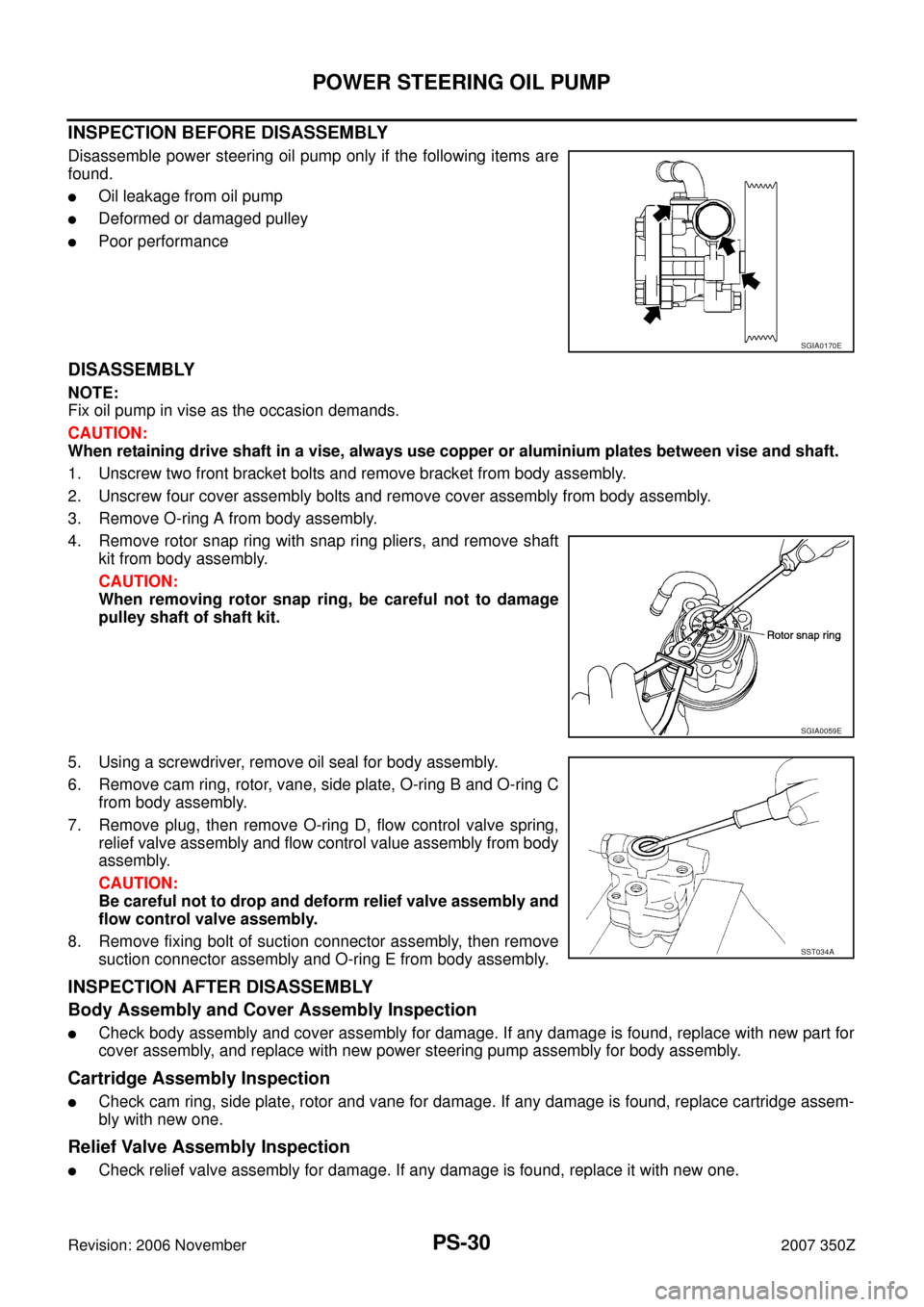
COMPONENTS
SGIA0376E
1. Plug 2. O-ring D 3. Flow control valve spring
4. Relief valve assembly 5. Flow control valve assembly 6. Shaft kit
7. Oil seal 8. Bracket 9. Body assembly
10. Suction connector assembly 11. O-ring E 12. O-ring C
13. O-ring B 14. Cartridge assembly 15. O-ring A
16. Cover assembly 17. Side plate 18. Vane
19. Rotor snap ring 20. Cam ring 21. Rotor
22. Dowel pin
SGIA0774E
Page 30 of 36

PS-30
POWER STEERING OIL PUMP
Revision: 2006 November2007 350Z
INSPECTION BEFORE DISASSEMBLY
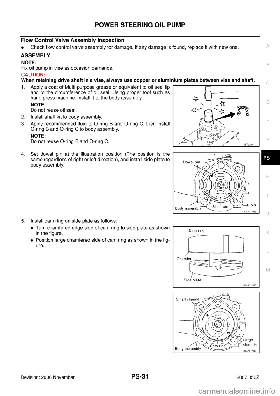
Disassemble power steering oil pump only if the following items are
found.
�Oil leakage from oil pump
�Deformed or damaged pulley
�Poor performance
DISASSEMBLY
NOTE:
Fix oil pump in vise as the occasion demands.
CAUTION:
When retaining drive shaft in a vise, always use copper or aluminium plates between vise and shaft.
1. Unscrew two front bracket bolts and remove bracket from body assembly.
2. Unscrew four cover assembly bolts and remove cover assembly from body assembly.
3. Remove O-ring A from body assembly.
4. Remove rotor snap ring with snap ring pliers, and remove shaft
kit from body assembly.
CAUTION:
When removing rotor snap ring, be careful not to damage
pulley shaft of shaft kit.
5. Using a screwdriver, remove oil seal for body assembly.
6. Remove cam ring, rotor, vane, side plate, O-ring B and O-ring C
from body assembly.
7. Remove plug, then remove O-ring D, flow control valve spring,
relief valve assembly and flow control value assembly from body
assembly.
CAUTION:
Be careful not to drop and deform relief valve assembly and
flow control valve assembly.
8. Remove fixing bolt of suction connector assembly, then remove
suction connector assembly and O-ring E from body assembly.
INSPECTION AFTER DISASSEMBLY
Body Assembly and Cover Assembly Inspection
�Check body assembly and cover assembly for damage. If any damage is found, replace with new part for
cover assembly, and replace with new power steering pump assembly for body assembly.
Cartridge Assembly Inspection
�Check cam ring, side plate, rotor and vane for damage. If any damage is found, replace cartridge assem-
bly with new one.
Relief Valve Assembly Inspection
�Check relief valve assembly for damage. If any damage is found, replace it with new one.
SGIA0170E
SGIA0059E
SST034A
Page 31 of 36

POWER STEERING OIL PUMP
PS-31
C
D
E
F
H
I
J
K
L
MA
B
PS
Revision: 2006 November2007 350Z
Flow Control Valve Assembly Inspection
�Check flow control valve assembly for damage. If any damage is found, replace it with new one.
ASSEMBLY
NOTE:
Fix oil pump in vise as occasion demands.
CAUTION:
When retaining drive shaft in a vise, always use copper or aluminium plates between vise and shaft.
1. Apply a coat of Multi-purpose grease or equivalent to oil seal lip
and to the circumference of oil seal. Using proper tool such as
hand press machine, install it to the body assembly.
NOTE:
Do not reuse oil seal.
2. Install shaft kit to body assembly.
3. Apply recommended fluid to O-ring B and O-ring C, then install
O-ring B and O-ring C to body assembly.
NOTE:
Do not reuse O-ring B and O-ring C.
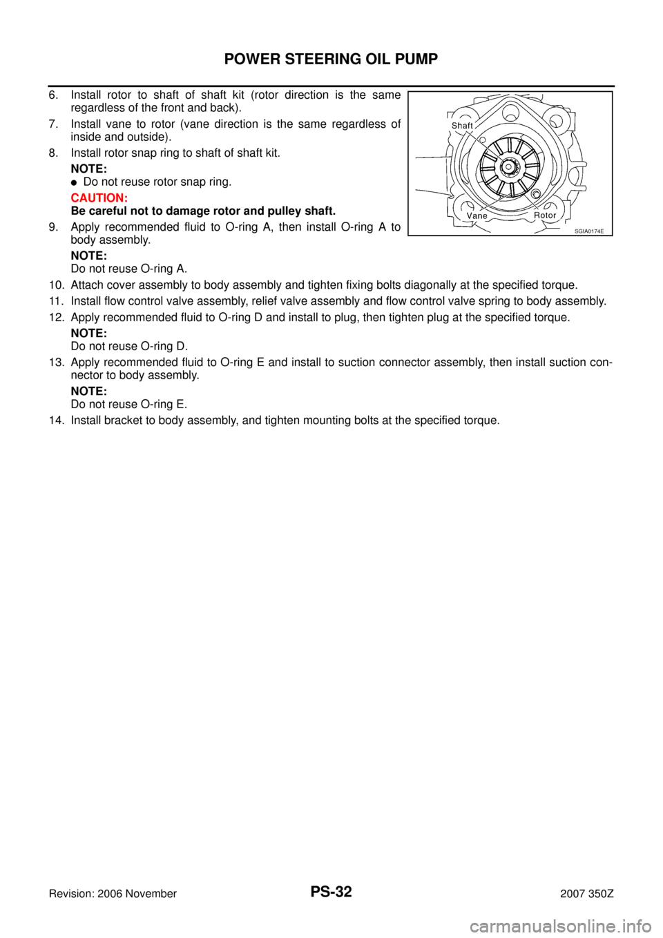
4. Set dowel pin at the illustration position (The position is the
same regardless of right or left direction), and install side plate to
body assembly.
5. Install cam ring on side plate as follows;
�Turn chamfered edge side of cam ring to side plate as shown
in the figure.
�Position large chamfered side of cam ring as shown in the fig-
ure.
SST038A
SGIA0171E
SGIA0172E
SGIA0173E
Page 32 of 36

PS-32
POWER STEERING OIL PUMP
Revision: 2006 November2007 350Z
6. Install rotor to shaft of shaft kit (rotor direction is the same
regardless of the front and back).
7. Install vane to rotor (vane direction is the same regardless of
inside and outside).
8. Install rotor snap ring to shaft of shaft kit.
NOTE:
�Do not reuse rotor snap ring.
CAUTION:
Be careful not to damage rotor and pulley shaft.
9. Apply recommended fluid to O-ring A, then install O-ring A to
body assembly.
NOTE:
Do not reuse O-ring A.
10. Attach cover assembly to body assembly and tighten fixing bolts diagonally at the specified torque.
11. Install flow control valve assembly, relief valve assembly and flow control valve spring to body assembly.
12. Apply recommended fluid to O-ring D and install to plug, then tighten plug at the specified torque.
NOTE:
Do not reuse O-ring D.
13. Apply recommended fluid to O-ring E and install to suction connector assembly, then install suction con-
nector to body assembly.
NOTE:
Do not reuse O-ring E.
14. Install bracket to body assembly, and tighten mounting bolts at the specified torque.
SGIA0174E
Page 34 of 36
PS-34
HYDRAULIC LINE
Revision: 2006 November2007 350Z
1. Reservoir tank 2. Reservoir tank bracket 3. Hose & tube assembly
4. Suction hose 5. Oil pressure sensor 6. Eye bolt
7. Oil cooler 8. Copper washer 9. Power steering oil pump
10. Steering gear assembly 11. Common bolt 12. Oil pump bracket
13. Clip
Page:
< prev 1-8 9-16 17-24