Page 3 of 36
PREPARATION
PS-3
C
D
E
F
H
I
J
K
L
MA
B
PS
Revision: 2006 November2007 350Z
PREPARATIONPFP:00002
Special Service ToolsNGS00004
The actual shapes of Kent-Moore tools may differ from those of special service tools illustrated here.
Tool number
(Kent-Moore No.)
Tool nameDescription
ST27180001
(J-25726-A)
Steering wheel pullerRemoving steering wheel
HT72520000
(J-25730-A)
Ball joint remover
a: 33 mm (1.30 in)
b: 50 mm (1.97 in)
r: 11.5 mm (0.453 in)Removing outer socket ball joint
ST3127S000
(See J-25765-A)
Preload gauge
1. GG9103000
(J-25765-A)
Torque wrench
2. HT62940000
( – )
Socket adapter
3. HT62900000
( – )
Socket adapterInspecting of rotating torque
KV48104400
( – )
Teflon ring installation tool
a: 50 mm (1.97 in) dia.
b: 36 mm (1.42 in) dia.
c: 100 mm (3.94 in)Installing of rack Teflon ring
KV48103400
( – )
Torque adapterInspecting rotating torque
S-NT544
NT546
S-NT541
S-NT550
ZZA0824D
Page 5 of 36
 TROUBLESHOOTING
PS-5
C
D
E
F
H
I
J
K
L
MA
B
PS
Revision: 2006 November2007 350Z
NOISE, VIBRATION AND HARSHNESS (NVH) TROUBLESHOOTINGPFP:00003
NVH Troubleshooting C")
NOISE, VIBRATION AND HARSHNESS (NVH) TROUBLESHOOTING
PS-5
C
D
E
F
H
I
J
K
L
MA
B
PS
Revision: 2006 November2007 350Z
NOISE, VIBRATION AND HARSHNESS (NVH) TROUBLESHOOTINGPFP:00003
NVH Troubleshooting ChartNGS00006
Use chart below to help you find the cause of the symptom. If necessary, repair or replace these parts.
×: ApplicableReference page
PS-6PS-6PS-21PS-21PS-21PS-6PS-7PS-21EM-12PS-7PS-15PS-17PS-10PS-10PS-17
NVH in PR section
NVH in RFD section
NVH in FAX, RAX, FSU, RSU section
NVH in WT section
NVH in WT section
NVH in RAX section
NVH in BR section
Possible cause and suspected parts
Fluid level
Air in hydraulic system
Outer socket ball joint swinging force
Outer socket ball joint sliding torque
Outer socket ball joint end play
Steering fluid leakage
Steering wheel play
Steering gear rack sliding force
Drive belt looseness
Improper steering wheel
Improper installation or looseness of tilt lock lever
Mounting rubber deterioration
Steering column deformation or damage
Improper installation or looseness of steering column
Steering linkage looseness
PROPELLER SHAFT
DIFFERENTIAL
AXLE and SUSPENSION
TIRES
ROAD WHEEL
DRIVE SHAFT
BRAKES
SymptomNoise× × ××××× × × ×××××× ×
Shake××× × ×××× ×
Vibration××××× × ×× ×
Shimmy××× × ××× ×
Judder××××××
Page 9 of 36
STEERING WHEEL
PS-9
C
D
E
F
H
I
J
K
L
MA
B
PS
Revision: 2006 November2007 350Z
Removal and InstallationNGS0000B
REMOVAL
NOTE:
When reconnecting spiral cable, fix cable with a tape so that fixing case and rotating part keep aligned. This
will omit neutral position alignment procedure during spiral cable installation.
1. Set vehicle to the straight-ahead position.
2. Remove driver air bag module. Refer to SRS-40, "
Removal and Installation" .
3. Remove steering wheel lock nut after steering is locked.
4. Remove steering wheel with the steering wheel puller A.
INSTALLATION
Installation is the reverse order of removal. For tightening torque, refer to PS-10, "Removal and Installation" .
NOTE:
Check the spiral cable neutral position after replacing or rotating spiral cable. Refer to SRS-42, "
Removal and
Installation" . Tool number A: ST27180001 (J-25726-A)
SGIA1323E
Page 13 of 36
STEERING COLUMN
PS-13
C
D
E
F
H
I
J
K
L
MA
B
PS
Revision: 2006 November2007 350Z
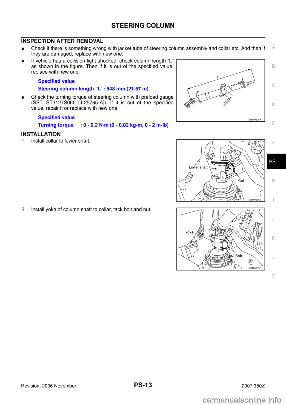
INSPECTION AFTER REMOVAL
�Check if there is something wrong with jacket tube of steering column assembly and collar etc. And then if
they are damaged, replace with new one.
�If vehicle has a collision light shocked, check column length “L”
as shown in the figure. Then if it is out of the specified value,
replace with new one.
�Check the turning torque of steering column with preload gauge
(SST: ST3127S000 [J-25765-A]). If it is out of the specified
value, repair it or replace with new one.
INSTALLATION
1. Install collar to lower shaft.
2. Install yoke of column shaft to collar, tack bolt and nut.Specified value
Steering column length “L”: 548 mm (21.57 in)
Specified value
Turning torque : 0 - 0.2 N·m (0 - 0.02 kg-m, 0 - 2 in-lb)
SGIA0306J
SGIA0356E
SGIA0353E
Page 14 of 36
PS-14
STEERING COLUMN
Revision: 2006 November2007 350Z
3. Put steering column assembly (installation hole “P”) on bolt for
steering member side and install nut “A” then tighten it together
with the other bolts at the specified torque.
4. Connect yoke and collar with bolt, tighten nut at the specified
torque.
INSPECTION AFTER INSTALLATION
�After installing steering column to vehicle, check tilt device and
its operation range “L
1” , “L2” .
�Check if steering operation can turn to the end of the left and
right smoothly.
SGIA0371E
Tilt operating range “L1 ” : 28 - 32 mm (1.10 - 1.26 in)
“L
2 ” : 13 - 17 mm (0.51 - 0.67 in)
SGIA1456E
Page 16 of 36

PS-16
STEERING COLUMN
Revision: 2006 November2007 350Z
c. Lock adjusting bolt, then remove lock nut.
d. Remove adjusting bolt, adjusting stopper, column mounting
bracket, tilt lever stopper and tilt lever from jacket tube.
INSPECTION AFTER DISASSEMBLY
�Check if there is something wrong with steering column shaft and bearing. And then if they are damaged,
replace with new one.
�Check if there is something wrong with the component of tilt device. And then if it is damaged, replace
with new one.
ASSEMBLY
1. Install tilt device to jacket tube. Refer to PS-15, "Disassembly and Assembly" .
NOTE:
�Turn tilt lever to unlock side while at work to make it easier.
�That can avoid column shaft's sudden descent when tilt lever
is operated on vehicle.
2. When tilt lever is in the locked position (operation range is about
40°), tighten lock nut at the specified torque to make tilt lever
locked.
3. Apply grease to the part shown in the figure of component. Refer
to PS-15, "
Disassembly and Assembly" .
4. Install steering column shaft to jacket tube, tighten steering col-
umn shaft lock nut at the specified torque.
SGIA0343E
SGIA0344E
SGIA0346E
Tightening torque:
13.5 - 18.6 N·m (1.4 - 1.8 kg-m, 10 - 13 ft-lb)
Tightening torque : 25 - 34 N·m (2.6 - 3.4 kg-m, 19 - 25 ft-lb)
SGIA0347E
Page 18 of 36

PS-18
POWER STEERING GEAR AND LINKAGE
Revision: 2006 November2007 350Z
8. Loosen bolt on upper yoke of lower joint and remove bolt on
lower yoke of joint, then slide lower joint into lower shaft. Sepa-
rate steering gear assembly from lower shaft.
9. Tack bolt on upper yoke of lower joint, fix lower joint to lower
shaft.
10. Remove the fixing bolt and remove steering gear assembly, rack
mounting bracket and insulator from vehicle.
INSTALLATION
�Refer to PS-17, "Removal and Installation" for tightening torque. Install in the reverse order of removal.
NOTE:
Refer to component parts location and do not reuse non-reusable parts.
�After removing/installing or replacing steering components, check wheel alignment. Refer to FSU-6,
"Wheel Alignment Inspection" .
�When steering wheel is set in the straight ahead direction, con-
firm slit of lower joint fits with the projection on rear cover cap,
furthermore marking position on steering gear assembly nearly
fits with the projection on rear cover cap.
�After installation, bleed air from piping. Refer to PS-6, "Air
Bleeding Hydraulic System" .
SGIA0367E
SGIA0348E
SGIA1753E
Page 21 of 36
 with a
dryer, then remove it and O-ring A from rack assem")
POWER STEERING GEAR
PS-21
C
D
E
F
H
I
J
K
L
MA
B
PS
Revision: 2006 November2007 350Z
11. Heat rack Teflon ring to approximately 40°C (104°F) with a
dryer, then remove it and O-ring A from rack assembly.
CAUTION:
Be careful not to damage rack. If it is damaged, change to a
new one to avoid oil leaks.
12. Use a taped 29 mm (1.14 in) socket and an extension bar.
Remove rack oil seal from gear housing assembly.
CAUTION:
Be careful not to damage gear housing assembly and cylin-
der inner wall. If it is damaged, gear housing assembly
must be replaced. Otherwise, oil leaks will result.
INSPECTION AFTER DISASSEMBLY
Boot
Check boot for cracks and deformation. Replace it, if necessary.
Rack Assembly
Check rack for damage and wear. Replace it, if necessary.
Gear-sub Assembly
�Check pinion gear for damage or wear. Replace if necessary.
�Rotate pinion and check for torque variation or rattle. Replace if necessary.
Gear Housing Assembly
Check gear housing assembly for damage and scratches (inner wall). Replace it, if necessary.
Outer Socket and Inner Socket
Swing Torque
�Hook a spring balance at the point shown in the figure. Confirm
if the reading is within the specification. When ball stud and
inner socket start moving the measured value must be within the
specification. If the reading is outside the specification, replace
socket.
SGIA0151E
SGIA0179E
SGIA0358E


 on bolt for
steering member side and install nut “A” then tighten it together
wit")