Page 22 of 36
PS-22
POWER STEERING GEAR
Revision: 2006 November2007 350Z
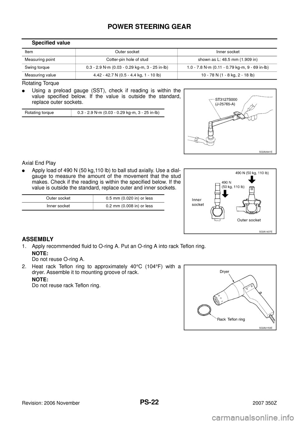
Specified value
Rotating Torque
�Using a preload gauge (SST), check if reading is within the
value specified below. If the value is outside the standard,
replace outer sockets.
Axial End Play
�Apply load of 490 N (50 kg,110 lb) to ball stud axially. Use a dial-
gauge to measure the amount of the movement that the stud
makes. Check if the reading is within the specified below. If the
value is outside the standard, replace outer and inner sockets.
ASSEMBLY
1. Apply recommended fluid to O-ring A. Put an O-ring A into rack Teflon ring.
NOTE:
Do not reuse O-ring A.
2. Heat rack Teflon ring to approximately 40°C (104°F) with a
dryer. Assemble it to mounting groove of rack.
NOTE:
Do not reuse rack Teflon ring.
Item Outer socket Inner socket
Measuring point Cotter-pin hole of stud shown as L: 48.5 mm (1.909 in)
Swing torque 0.3 - 2.9 N·m (0.03 - 0.29 kg-m, 3 - 25 in-lb) 1.0 - 7.8 N·m (0.11 - 0.79 kg-m, 9 - 69 in-lb)
Measuring value 4.42 - 42.7 N (0.5 - 4.4 kg, 1 - 10 lb) 10 - 78 N (1 - 8 kg, 2 - 18 lb)
Rotating torque 0.3 - 2.9 N·m (0.03 - 0.29 kg-m, 3 - 25 in-lb)
SGIA0941E
Outer socket 0.5 mm (0.020 in) or less
Inner socket 0.2 mm (0.008 in) or less
SGIA1437E
SGIA0153E
Page 24 of 36
![NISSAN 350Z 2007 Z33 Power Steering System Workshop Manual PS-24
POWER STEERING GEAR
Revision: 2006 November2007 350Z
c. When installing outer rack oil seal, cover the end of rack with an
OHP sheet [70 mm (2.76 in) × 100 mm (3.94 in)]. It will avoid
damaging NISSAN 350Z 2007 Z33 Power Steering System Workshop Manual PS-24
POWER STEERING GEAR
Revision: 2006 November2007 350Z
c. When installing outer rack oil seal, cover the end of rack with an
OHP sheet [70 mm (2.76 in) × 100 mm (3.94 in)]. It will avoid
damaging](/manual-img/5/779/w960_779-23.png)
PS-24
POWER STEERING GEAR
Revision: 2006 November2007 350Z
c. When installing outer rack oil seal, cover the end of rack with an
OHP sheet [70 mm (2.76 in) × 100 mm (3.94 in)]. It will avoid
damaging rack oil seal. Then place oil seal on sheet. Pull rack oil
seal along with OHP sheet until they pass rack end. Then
remove OHP sheet.
d. Install end cover assembly to rack, move it to gear housing
assembly.
5. Using a 42 mm (1.65 in) open head (suitable tool), tighten end
cover assembly at the specified torque.
CAUTION:
Do not damage rack surface. If it is damaged, it may cause
oil leaks. Replace rack assembly.
6. After tightening end cover assembly, caulk cylinder at one point
as shown in the figure using a punch. This will prevent end cover
from getting loose.
7. Apply recommended fluid to O-ring B. Install O-ring B to gear
housing assembly.
NOTE:
Do not reuse O-ring B.
8. Install gear-sub assembly to gear housing assembly.
9. Decide neutral position of rack.
10. Install the projection part (Tip) of rear cover cap to gear-sub
assembly as shown in the figure.
SGIA0157E
SST081B
SGIA0158E
Rack stroke “L” : 64.5 mm (2.539 in)
SGIA0629J
SGIA1753E
Page 25 of 36
POWER STEERING GEAR
PS-25
C
D
E
F
H
I
J
K
L
MA
B
PS
Revision: 2006 November2007 350Z
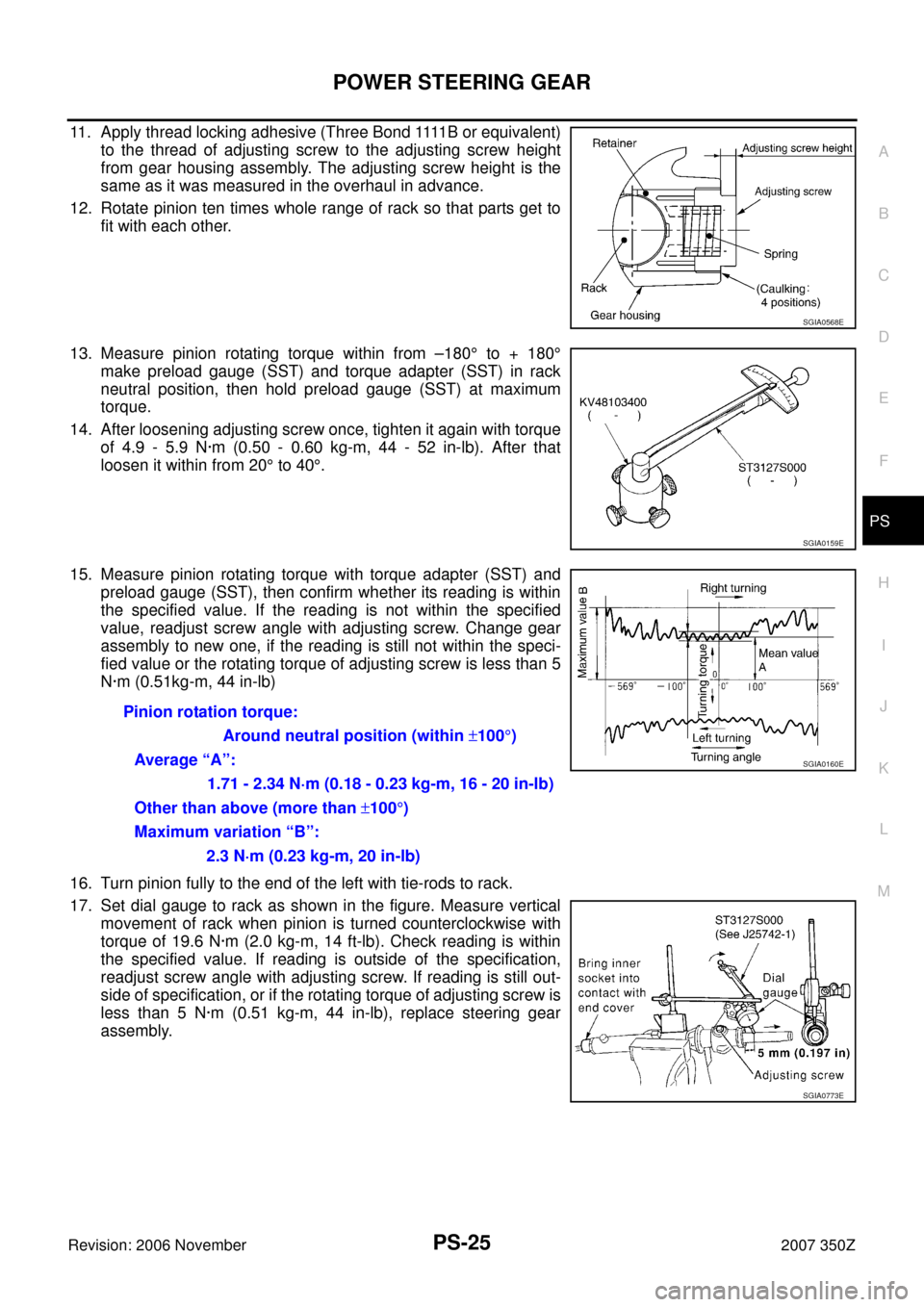
11. Apply thread locking adhesive (Three Bond 1111B or equivalent)
to the thread of adjusting screw to the adjusting screw height
from gear housing assembly. The adjusting screw height is the
same as it was measured in the overhaul in advance.
12. Rotate pinion ten times whole range of rack so that parts get to
fit with each other.
13. Measure pinion rotating torque within from –180° to + 180°
make preload gauge (SST) and torque adapter (SST) in rack
neutral position, then hold preload gauge (SST) at maximum
torque.
14. After loosening adjusting screw once, tighten it again with torque
of 4.9 - 5.9 N·m (0.50 - 0.60 kg-m, 44 - 52 in-lb). After that
loosen it within from 20° to 40°.
15. Measure pinion rotating torque with torque adapter (SST) and
preload gauge (SST), then confirm whether its reading is within
the specified value. If the reading is not within the specified
value, readjust screw angle with adjusting screw. Change gear
assembly to new one, if the reading is still not within the speci-
fied value or the rotating torque of adjusting screw is less than 5
N·m (0.51kg-m, 44 in-lb)
16. Turn pinion fully to the end of the left with tie-rods to rack.
17. Set dial gauge to rack as shown in the figure. Measure vertical
movement of rack when pinion is turned counterclockwise with
torque of 19.6 N·m (2.0 kg-m, 14 ft-lb). Check reading is within
the specified value. If reading is outside of the specification,
readjust screw angle with adjusting screw. If reading is still out-
side of specification, or if the rotating torque of adjusting screw is
less than 5 N·m (0.51 kg-m, 44 in-lb), replace steering gear
assembly.
SGIA0568E
SGIA0159E
Pinion rotation torque:
Around neutral position (within ±100°)
Average “A”:
1.71 - 2.34 N·m (0.18 - 0.23 kg-m, 16 - 20 in-lb)
Other than above (more than ±100°)
Maximum variation “B”:
2.3 N·m (0.23 kg-m, 20 in-lb)
SGIA0160E
SGIA0773E
Page 27 of 36
POWER STEERING GEAR
PS-27
C
D
E
F
H
I
J
K
L
MA
B
PS
Revision: 2006 November2007 350Z
e. After twisting wire 4 to 4.5 turns, bend cut end of wire. Cut end of
wire should not touch boot. Be sure wire end is at least 5 mm
(0.20 in) away from clearance for tube.
22. Install cylinder tubes to gear housing assembly.
23. Tighten lightly inner socket in specified length “L”, then tighten
lock nut at specified torque. Refer to PS-19, "
COMPONENTS" .
Reconfirm if inner socket length is within limit of specified length
“L”.
CAUTION:
Perform toe-in adjustment after this procedure. Length
achieved after toe-in adjustment is not necessarily value
given here.
SGIA0166E
SGIA0360E
Inner socket length “L” : 106.3 mm (4.19 in)
SGIA0167E
Page 29 of 36
POWER STEERING OIL PUMP
PS-29
C
D
E
F
H
I
J
K
L
MA
B
PS
Revision: 2006 November2007 350Z
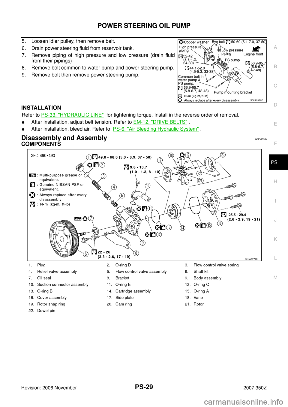
5. Loosen idler pulley, then remove belt.
6. Drain power steering fluid from reservoir tank.
7. Remove piping of high pressure and low pressure (drain fluid
from their pipings)
8. Remove bolt common to water pump and power steering pump.
9. Remove bolt then remove power steering pump.
INSTALLATION
Refer to PS-33, "HYDRAULIC LINE" for tightening torque. Install in the reverse order of removal.
�After installation, adjust belt tension. Refer to EM-12, "DRIVE BELTS" .
�After installation, bleed air. Refer to PS-6, "Air Bleeding Hydraulic System" .
Disassembly and AssemblyNGS0000J
COMPONENTS
SGIA0376E
1. Plug 2. O-ring D 3. Flow control valve spring
4. Relief valve assembly 5. Flow control valve assembly 6. Shaft kit
7. Oil seal 8. Bracket 9. Body assembly
10. Suction connector assembly 11. O-ring E 12. O-ring C
13. O-ring B 14. Cartridge assembly 15. O-ring A
16. Cover assembly 17. Side plate 18. Vane
19. Rotor snap ring 20. Cam ring 21. Rotor
22. Dowel pin
SGIA0774E
Page 32 of 36
PS-32
POWER STEERING OIL PUMP
Revision: 2006 November2007 350Z
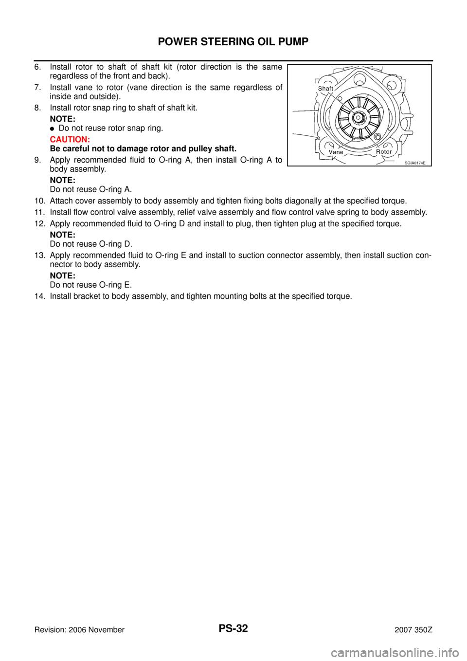
6. Install rotor to shaft of shaft kit (rotor direction is the same
regardless of the front and back).
7. Install vane to rotor (vane direction is the same regardless of
inside and outside).
8. Install rotor snap ring to shaft of shaft kit.
NOTE:
�Do not reuse rotor snap ring.
CAUTION:
Be careful not to damage rotor and pulley shaft.
9. Apply recommended fluid to O-ring A, then install O-ring A to
body assembly.
NOTE:
Do not reuse O-ring A.
10. Attach cover assembly to body assembly and tighten fixing bolts diagonally at the specified torque.
11. Install flow control valve assembly, relief valve assembly and flow control valve spring to body assembly.
12. Apply recommended fluid to O-ring D and install to plug, then tighten plug at the specified torque.
NOTE:
Do not reuse O-ring D.
13. Apply recommended fluid to O-ring E and install to suction connector assembly, then install suction con-
nector to body assembly.
NOTE:
Do not reuse O-ring E.
14. Install bracket to body assembly, and tighten mounting bolts at the specified torque.
SGIA0174E
Page 35 of 36
SERVICE DATA AND SPECIFICATIONS (SDS)
PS-35
C
D
E
F
H
I
J
K
L
MA
B
PS
Revision: 2006 November2007 350Z
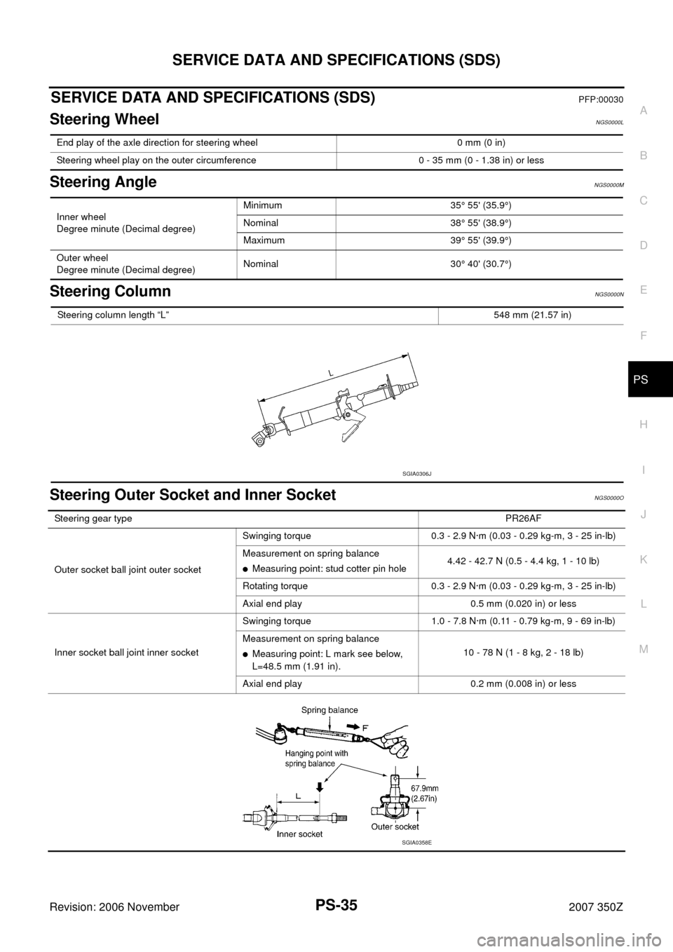
SERVICE DATA AND SPECIFICATIONS (SDS)PFP:00030
Steering WheelNGS0000L
Steering AngleNGS0000M
Steering ColumnNGS0000N
Steering Outer Socket and Inner SocketNGS0000O
End play of the axle direction for steering wheel 0 mm (0 in)
Steering wheel play on the outer circumference 0 - 35 mm (0 - 1.38 in) or less
Inner wheel
Degree minute (Decimal degree)Minimum 35° 55' (35.9°)
Nominal 38° 55' (38.9°)
Maximum 39° 55' (39.9°)
Outer wheel
Degree minute (Decimal degree)Nominal 30° 40' (30.7°)
Steering column length “L”548 mm (21.57 in)
SGIA0306J
Steering gear typePR26AF
Outer socket ball joint outer socketSwinging torque 0.3 - 2.9 N·m (0.03 - 0.29 kg-m, 3 - 25 in-lb)
Measurement on spring balance
�Measuring point: stud cotter pin hole4.42 - 42.7 N (0.5 - 4.4 kg, 1 - 10 lb)
Rotating torque 0.3 - 2.9 N·m (0.03 - 0.29 kg-m, 3 - 25 in-lb)
Axial end play 0.5 mm (0.020 in) or less
Inner socket ball joint inner socketSwinging torque 1.0 - 7.8 N·m (0.11 - 0.79 kg-m, 9 - 69 in-lb)
Measurement on spring balance
�Measuring point: L mark see below,
L=48.5 mm (1.91 in).10 - 78 N (1 - 8 kg, 2 - 18 lb)
Axial end play 0.2 mm (0.008 in) or less
SGIA0358E