PARKING BRAKE SYSTEM
PB-3
C
D
E
G
H
I
J
K
L
MA
B
PB
Revision: 2006 November2007 350Z
PARKING BRAKE SYSTEMPFP:36010
On-Vehicle ServiceNFS0001F
LEVER STROKE
�When parking brake lever is operated with a force of 196 N (20 kg, 44 lb), check that the stroke is within
the specified number of notches. (Check it by listening and counting the ratchet clicks.)
INSPECT COMPONENTS
�Make sure the components are attached properly (check for looseness, backlash, etc.).
�Check parking lever assembly for bend, damage and cracks, and replace if necessary.
�Check that there is no wear or damage to the cable, and replace if there is.
�Inspecting parking brake warning lamp switch is inspected and exchange if there is a faulty.
ADJUSTMENT
�To perform adjustment operations, remove tire from the vehicle with power tool.
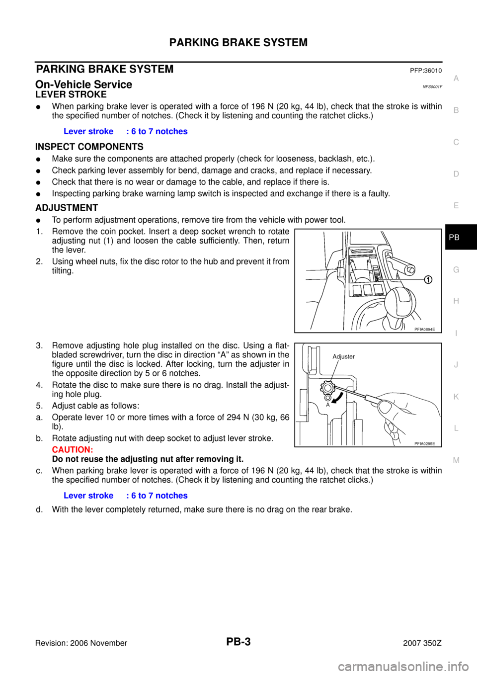
1. Remove the coin pocket. Insert a deep socket wrench to rotate
adjusting nut (1) and loosen the cable sufficiently. Then, return
the lever.
2. Using wheel nuts, fix the disc rotor to the hub and prevent it from
tilting.
3. Remove adjusting hole plug installed on the disc. Using a flat-
bladed screwdriver, turn the disc in direction “A” as shown in the
figure until the disc is locked. After locking, turn the adjuster in
the opposite direction by 5 or 6 notches.
4. Rotate the disc to make sure there is no drag. Install the adjust-
ing hole plug.
5. Adjust cable as follows:
a. Operate lever 10 or more times with a force of 294 N (30 kg, 66
lb).
b. Rotate adjusting nut with deep socket to adjust lever stroke.
CAUTION:
Do not reuse the adjusting nut after removing it.
c. When parking brake lever is operated with a force of 196 N (20 kg, 44 lb), check that the stroke is within
the specified number of notches. (Check it by listening and counting the ratchet clicks.)
d. With the lever completely returned, make sure there is no drag on the rear brake.Lever stroke : 6 to 7 notches
PFIA0894E
Lever stroke : 6 to 7 notches
PFIA0295E
PARKING BRAKE SHOE
PB-5
C
D
E
G
H
I
J
K
L
MA
B
PB
Revision: 2006 November2007 350Z
PARKING BRAKE SHOEPFP:44060
ComponentsNFS0001I
Removal and InstallationNFS0001J
REMOVAL
WARNING:
Clean brakes with a vacuum dust collector to minimize the hazard of air borne particles or other mate-
rials.
Be careful of the following:
�Remove the disc rotor only with the parking brake lever completely in the returned position.
�If disc rotor cannot be removed, remove as follows:
1. Fix the disc rotor in place with wheel nuts and remove disc rotor
plug. Using a flat-bladed screwdriver, rotate star wheel on the
adjuster assembly in direction “B” to retract and loosen brake
shoes.
1. Return spring 2. Adjuster assembly 3. Shoe
4. Anti-rattle pin 5. Retainer 6. Anti-rattle spring
7. Toggle lever
PFIA0243E
PFIA0309E
SERVICE DATA AND SPECIFICATIONS (SDS)
PB-7
C
D
E
G
H
I
J
K
L
MA
B
PB
Revision: 2006 November2007 350Z
SERVICE DATA AND SPECIFICATIONS (SDS)PFP:00030
Parking Drum BrakeNFS0001K
Parking Brake ControlNFS0001L
Brake liningStandard thickness (new) 3.2 mm (0.126 in)
Wear limit thickness 1.5 mm (0.059 in)
Drum (disc)Standard inner diameter (new) 172 mm (6.77 in) dia.
Wear limit of inner diameter 173 mm (6.81 in) dia.
Control typeCenter lever
Number of notches [under force of 196 N (20 kg,44 lb)] 6 – 7 notches
Number of notches when warning lamp comes on 1 notch


PB-7
C
D
E
G
H
I
J
K
L
MA
B
PB
Revision: 2006 November2007 350Z
SERVICE DATA AND SPECIFICATIONS (SDS)PFP:00030
Parking Drum BrakeNFS0001K
Parking Brake ControlNFS")