Page 29 of 62

TRANSMISSION ASSEMBLY
MT-29
D
E
F
G
H
I
J
K
L
MA
B
MT
Revision: 2006 November2007 350Z
10. Remove rear extension mounting bolts. Using a soft hammer,
tap rear extension assembly to remove.
CAUTION:
Do not hold control lever housing to prevent bushing of
control lever housing from deformation when moving trans-
mission assembly.
11. Remove control lever housing mounting bolts, and remove con-
trol lever housing from the rear extension.
12. Remove striking rod oil seal from the rear extension. Refer to
MT-22, "
Case Components" .
CAUTION:
Be careful not to damage rear extension.
13. Remove rear extension oil gutter and cap from the rear extension. Refer to MT-22, "
Case Components" .
14. Remove reverse idler thrust washer, revers idler gear, and
reverse idler needle bearing from the reverse idler shaft.
15. Remove reverse idler shaft from the adapter plate.
16. Remove front cover mounting bolts, then remove front cover and
front cover gasket from the transmission case.
17. Remove front cover oil seal from the front cover, using a flat-
bladed screwdriver.
CAUTION:
Be careful not to damage front cover mating surface.
PCIB0141E
PCIB0152E
PCIB1920E
SCIA1399E
Page 30 of 62
MT-30
TRANSMISSION ASSEMBLY
Revision: 2006 November2007 350Z
18. Remove baffle plate mounting nut from the transmission case.
19. Remove snap ring from the main drive gear bearing, using snap
ring pliers.
20. Using a soft hammer to carefully tap main shaft and counter
shaft from the transmission case side, and then separate
adapter plate and transmission case.
21. Remove counter front bearing from the transmission case.
22. Remove oil gutter and breather tube from the transmission case.
23. Remove filler plug, drain plug, and gaskets from transmission
case.
24. Remove bracket mounting bolt and then remove bracket from
transmission case.
SCIA1443E
SCIA1532E
SCIA1687E
PCIB0436E
Page 37 of 62

TRANSMISSION ASSEMBLY
MT-37
D
E
F
G
H
I
J
K
L
MA
B
MT
Revision: 2006 November2007 350Z
14. Using a press to remove 1st main gear and 3rd main gear.
CAUTION:
Be careful not to damage the baulk ring.
15. Remove 1st needle bearing.
16. Using a press to remove 1st gear bushing, 1st-2nd synchronizer
assembly, and 2nd main gear.
CAUTION:
Be aware that when using the press, if the main shaft gear
positioner catches on the V-block, etc., the main shaft could
be damaged.
17. Remove 2nd needle bearing.
18. After removing snap ring, using a press to remove 6th main gear
and 5th-6th synchronizer assembly.
19. Remove 6th needle bearing.
20. Using a press to remove the 3rd counter gear, 3rd-4th synchro-
nizer assembly, 4th counter gear, 4th needle bearing, 4th gear
bushing, 4th counter gear thrust washer, and counter rear bear-
ing inner race.
21. Remove 3rd needle bearing.
22. Using a press to remove the 3rd gear bushing.
CAUTION:
Do not use oil hole of 3rd gear bushing when press out.
SCIA1458E
SCIA1459E
SCIA1460E
SCIA1389E
PCIB1327E
Page 43 of 62
TRANSMISSION ASSEMBLY
MT-43
D
E
F
G
H
I
J
K
L
MA
B
MT
Revision: 2006 November2007 350Z
CAUTION:
When press fitting, install with the side having the three
boss edge oil grooves facing the rear side.
NOTE:
5th and 6th baulk rings have three spaces that four gear teeth
are missing as shown in the figure.
5. Select and install a snap ring so that the end play comes within
the standard value.
CAUTION:
Do not reuse snap ring.
6. Install 1st-2nd coupling sleeve and 1st-2nd shifting inserts into the 1st-2nd synchronizer hub.
CAUTION:
�Do not reuse 1st-2nd coupling sleeve and 1st-2nd synchronizer hub.
�Replace 1st-2nd coupling sleeve and 1st-2nd synchronizer hub as a set.
�Install 1st-2nd coupling sleeve with the thicker flange
faced the front side.
7. Install 1st-2nd spread springs in the 1st-2nd shifting inserts.
PCIB1363E
PCIB1330E
End play : 0 - 0.10 mm (0 - 0.004 in)
PCIB0609E
PCIB0610E
Page 44 of 62
MT-44
TRANSMISSION ASSEMBLY
Revision: 2006 November2007 350Z
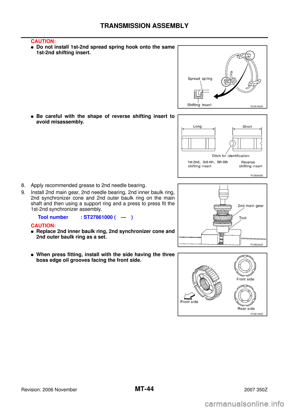
CAUTION:
�Do not install 1st-2nd spread spring hook onto the same
1st-2nd shifting insert.
�Be careful with the shape of reverse shifting insert to
avoid misassembly.
8. Apply recommended grease to 2nd needle bearing.
9. Install 2nd main gear, 2nd needle bearing, 2nd inner baulk ring,
2nd synchronizer cone and 2nd outer baulk ring on the main
shaft and then using a support ring and a press to press fit the
1st-2nd synchronizer assembly.
CAUTION:
�Replace 2nd inner baulk ring, 2nd synchronizer cone and
2nd outer baulk ring as a set.
�When press fitting, install with the side having the three
boss edge oil grooves facing the front side.
SCIA1600E
PCIB0608E
Tool number : ST27861000 ( — )
PCIB0202E
PCIB1364E
Page 47 of 62
TRANSMISSION ASSEMBLY
MT-47
D
E
F
G
H
I
J
K
L
MA
B
MT
Revision: 2006 November2007 350Z
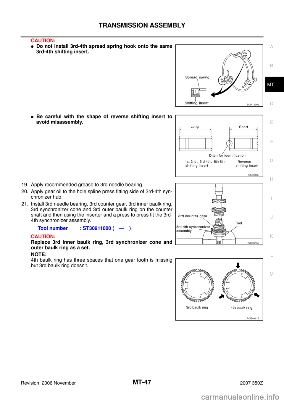
CAUTION:
�Do not install 3rd-4th spread spring hook onto the same
3rd-4th shifting insert.
�Be careful with the shape of reverse shifting insert to
avoid misassembly.
19. Apply recommended grease to 3rd needle bearing.
20. Apply gear oil to the hole spline press fitting side of 3rd-4th syn-
chronizer hub.
21. Install 3rd needle bearing, 3rd counter gear, 3rd inner baulk ring,
3rd synchronizer cone and 3rd outer baulk ring on the counter
shaft and then using the inserter and a press to press fit the 3rd-
4th synchronizer assembly.
CAUTION:
Replace 3rd inner baulk ring, 3rd synchronizer cone and
outer baulk ring as a set.
NOTE:
4th baulk ring has three spaces that one gear tooth is missing
but 3rd baulk ring doesn't.
SCIA1600E
PCIB0608E
Tool number : ST30911000 ( — )
PCIB0615E
PCIB0451E
Page 49 of 62

TRANSMISSION ASSEMBLY
MT-49
D
E
F
G
H
I
J
K
L
MA
B
MT
Revision: 2006 November2007 350Z
30. Install the adapter setting plate to adapter plate and then fixing
in adapter setting plate using a vise.
CAUTION:
Do not directly secure the surface in a vise.
31. Install magnet to adapter plate.
32. Install snap ring to mainshaft bearing.
CAUTION:
Do not reuse snap ring.
33. Install counter rear bearing onto the adapter plate using the drift.
CAUTION:
Replace counter rear bearing inner race, counter rear bear-
ing and counter rear bearing spacer as a set.
34. Apply recommended thread locking sealant to the end of the
bolts (first 3 to 4 threads), screw the bolts into the main shaft
bearing retainer, and tighten it to the specified torque. Refer to
MT-22, "
Case Components" .
�Use Genuine Medium Strength Thread Locking Sealant or
an equivalent. Refer to GI-45, "
RECOMMENDED CHEMI-
CAL PRODUCTS AND SEALANTS" .
CAUTION:
Remove old sealant and oil adhering to threads.
35. Install reverse coupling sleeve and reverse shifting inserts into the reverse synchronizer hub.
CAUTION:
�Do not reuse reverse coupling sleeve and reverse synchronizer hub.
�Replace reverse coupling sleeve and reverse synchronizer hub as a set.Tool number : ST22490000 ( — )
PCIB0254E
SCIA1691E
PCIB1375E
PCIB1238E
Page 54 of 62

MT-54
TRANSMISSION ASSEMBLY
Revision: 2006 November2007 350Z
14. Install 1st-2nd shift fork to the 1st-2nd coupling sleeve.
15. Install 1st-2nd fork rod to the 1st-2nd shift fork.
16. Using a pin punch to tap the retaining pin into the 1st-2nd shift
fork.
CAUTION:
Do not reuse retaining pin.
17. Install 3rd-4th shift fork to the 3rd-4th coupling sleeve.
18. Install 3rd-4th fork rod (reversal side) to the 3rd-4th shift fork.
19. Using a pin punch to tap the retaining pin into the 3rd-4th shift
fork (reversal side).
CAUTION:
Do not reuse retaining pin.
20. Apply recommended grease to interlock pin and check balls.
21. Install interlock pin and check balls to the adapter plate.
22. Install 3rd-4th fork rod to the adapter plate.
23. Install 3rd-4th fork rod bracket to the 3rd-4th fork rod.
24. Using a pin punch to tap the retaining pin into the 3rd-4th fork
rod bracket.
CAUTION:
Do not reuse retaining pin.
25. Apply recommended grease to check ball and then install check
ball and check ball spring into adapter plate.
26. Apply recommended sealant to threads of check ball plugs, and
tighten check ball plugs to the specified torque. Refer to MT-26,
"Shift Control Components" .
�Use Genuine Silicone RTV or an equivalent. Refer to GI-
45, "RECOMMENDED CHEMICAL PRODUCTS AND SEAL-
ANTS" .
CAUTION:
Remove old sealant and oil adhering to threads.
PCIB0602E
PCIB0601E
PCIB0146E
PCIB0145E
PCIB0144E