Page 78 of 172
LT-78
TURN SIGNAL AND HAZARD WARNING LAMPS
Revision: 2006 November2007 350Z
How to Proceed With Trouble DiagnosisNKS004YA
1. Confirm the symptom or customer complaint.
2. Understand operation description and function description. Refer to LT- 6 5 , "
System Description" .
3. Perform preliminary check. Refer to LT- 7 9 , "
Preliminary Check" .
4. Check symptom and repair or replace the cause of malfunction.
5. Do turn signal and hazard warning lamps operate normally? If YES, GO TO 6. If NO, GO TO 4.
6. INSPECTION END
42 GYBattery power
supplyOFF — Battery voltage
45 G/W Turn signal (left) ON Combination switch Turn left ON
46 PU/W Turn signal (right) ON Combination switch Turn right ON
52 B Ground ON — Approx. 0V
55 RBattery power
supplyOFF — Battery voltage Te r -
minal
No.Wire
colorSignal nameMeasuring condition
Reference value
Ignition
switchOperation or condition
SKIA3009J
SKIA3009J
Page 79 of 172
TURN SIGNAL AND HAZARD WARNING LAMPS
LT-79
C
D
E
F
G
H
I
J
L
MA
B
LT
Revision: 2006 November2007 350Z
Preliminary CheckNKS004YB
CHECK POWER SUPPLY AND GROUND CIRCUIT
1. CHECK FUSES AND FUSIBLE LINK
Check for blown fuses and fusible link.
Refer to LT- 6 9 , "
Wiring Diagram — TURN —" .
OK or NG
OK >> GO TO 2.
NG >> If fuse is blown, be sure to eliminate cause of malfunction before installing new fuse. Refer to PG-
4, "POWER SUPPLY ROUTING CIRCUIT" .
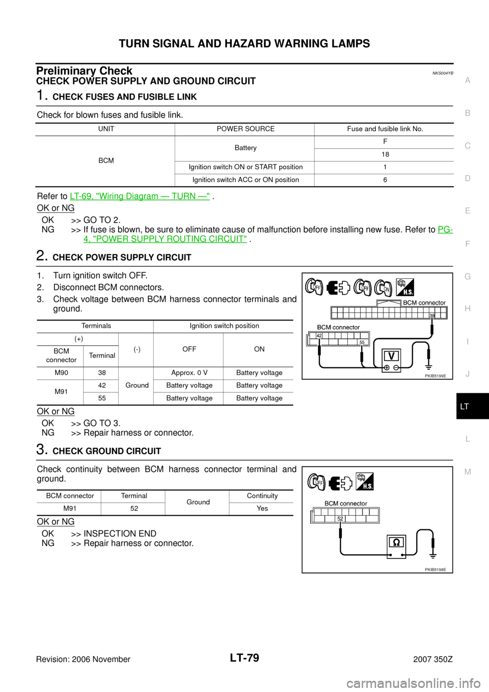
2. CHECK POWER SUPPLY CIRCUIT
1. Turn ignition switch OFF.
2. Disconnect BCM connectors.
3. Check voltage between BCM harness connector terminals and
ground.
OK or NG
OK >> GO TO 3.
NG >> Repair harness or connector.
3. CHECK GROUND CIRCUIT
Check continuity between BCM harness connector terminal and
ground.
OK or NG
OK >> INSPECTION END
NG >> Repair harness or connector.
UNIT POWER SOURCE Fuse and fusible link No.
BCMBatteryF
18
Ignition switch ON or START position 1
Ignition switch ACC or ON position 6
Terminals Ignition switch position
(+)
(-) OFF ON
BCM
connectorTerminal
M90 38
GroundApprox. 0 V Battery voltage
M9142 Battery voltage Battery voltage
55 Battery voltage Battery voltage
PKIB5199E
BCM connector Terminal
GroundContinuity
M91 52 Yes
PKIB5198E
Page 80 of 172

LT-80
TURN SIGNAL AND HAZARD WARNING LAMPS
Revision: 2006 November2007 350Z
CONSULT-III Function (BCM)NKS004YC
CONSULT-III can display each diagnostic item using the diagnostic test mode shown following.
DATA MONITOR
Display Item List
NOTE:
This item is displayed, but cannot be monitored.
ACTIVE TEST
Display Item List
BCM diagnosis part Diagnosis mode Description
FLASHERDATA MONITOR Displays BCM input data in real time.
ACTIVE TEST Operation of electrical loads can be checked by sending driving signal to them.
Monitor item Contents
IGN ON SW “ON/OFF” Displays “IGN position (ON)/OFF, ACC position (OFF)” judged from ignition switch signal.
HAZARD SW “ON/OFF” Displays “Hazard ON (ON)/Hazard OFF (OFF)” status, determined from hazard switch signal.
TURN SIGNAL R “ON/OFF” Displays “Turn right (ON)/Other (OFF)” status, determined from lighting switch signal.
TURN SIGNAL L “ON/OFF” Displays “Turn left (ON)/Other (OFF)” status, determined from lighting switch signal.
BRAKE SW
NOTE“OFF” —
Test item Description
FLASHER With a certain operation (OFF, RH, LH), turn signal lamp can be operated.
Page 81 of 172
TURN SIGNAL AND HAZARD WARNING LAMPS
LT-81
C
D
E
F
G
H
I
J
L
MA
B
LT
Revision: 2006 November2007 350Z
Turn Signal Lamp Does Not OperateNKS004YD
1. CHECK BULB
Check bulb standard of each turn signal lamp is correct.
OK or NG
OK >> GO TO 2.
NG >> Replace turn signal lamp bulb.
2. CHECK COMBINATION SWITCH INPUT SIGNAL
CONSULT-III DATA MONITOR
1. Select "TURN SIGNAL R" and "TURN SIGNAL L" of BCM data monitor item.
2. With operating the lighting switch, check the monitor status.
CHECK COMBINATION SWITCH
Refer to LT- 9 2 , "
Combination Switch Inspection" .
OK or NG
OK >> GO TO 3.
NG >> Check combination switch (lighting switch). Refer to LT- 9 2 , "
Combination Switch Inspection" .
3. ACTIVE TEST
CONSULT-III ACTIVE TEST
1. Select "FLASHER" of BCM active test item.
2. With operating the test item, check the turn signal lamp operation.
GO TO 4
OK or NG
OK >> Replace BCM. Refer to BCS-17, "Removal and Installation of BCM" .
NG >> GO TO 4.
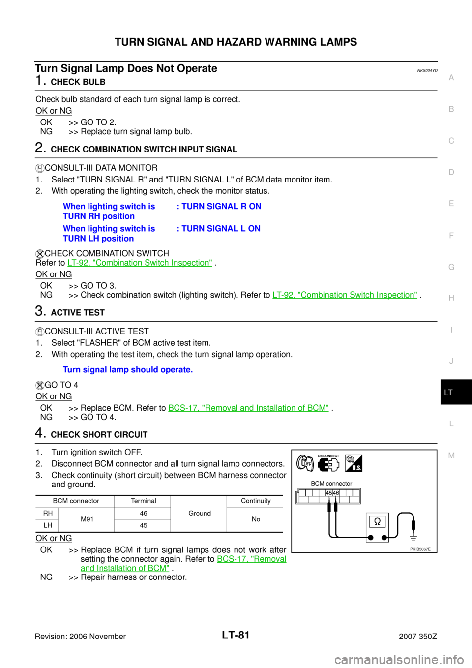
4. CHECK SHORT CIRCUIT
1. Turn ignition switch OFF.
2. Disconnect BCM connector and all turn signal lamp connectors.
3. Check continuity (short circuit) between BCM harness connector
and ground.
OK or NG
OK >> Replace BCM if turn signal lamps does not work after
setting the connector again. Refer to BCS-17, "
Removal
and Installation of BCM" .
NG >> Repair harness or connector.When lighting switch is
TURN RH position: TURN SIGNAL R ON
When lighting switch is
TURN LH position: TURN SIGNAL L ON
Turn signal lamp should operate.
BCM connector Terminal
GroundContinuity
RH
M9146
No
LH 45
PKIB5067E
Page 82 of 172
LT-82
TURN SIGNAL AND HAZARD WARNING LAMPS
Revision: 2006 November2007 350Z
Hazard Warning Lamp Does Not Operate But Turn Signal Lamp OperateNKS004YE
1. CHECK BULB
Make sure bulb standard of each turn signal lamp is correct.
OK or NG
OK >> GO TO 2.
NG >> Replace bulb.
2. CHECK HAZARD SWITCH INPUT SIGNAL
With CONSULT-III
1. Select "HAZARD SW" of BCM data monitor item.
2. With operating the hazard switch, check the monitor status.
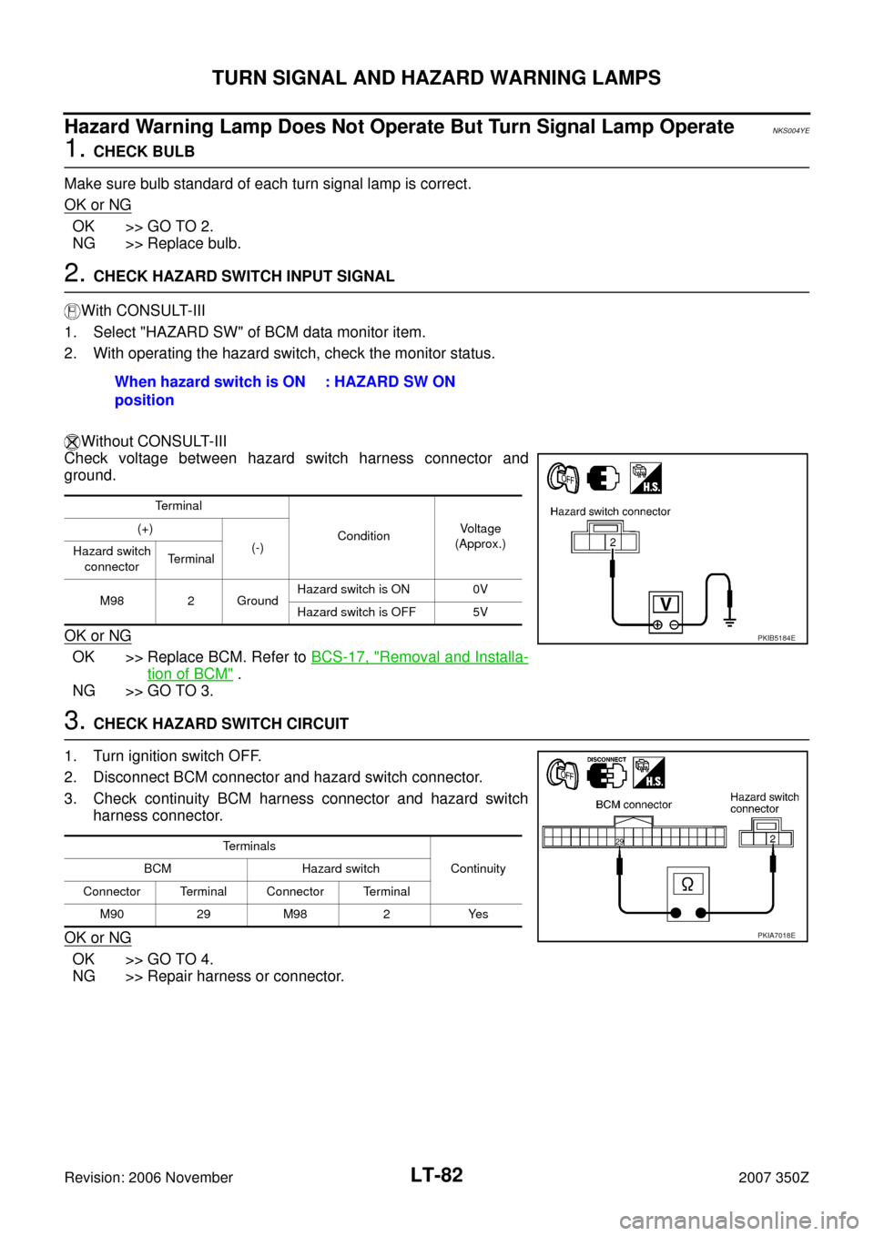
Without CONSULT-III
Check voltage between hazard switch harness connector and
ground.
OK or NG
OK >> Replace BCM. Refer to BCS-17, "Removal and Installa-
tion of BCM" .
NG >> GO TO 3.
3. CHECK HAZARD SWITCH CIRCUIT
1. Turn ignition switch OFF.
2. Disconnect BCM connector and hazard switch connector.
3. Check continuity BCM harness connector and hazard switch
harness connector.
OK or NG
OK >> GO TO 4.
NG >> Repair harness or connector.When hazard switch is ON
position : HAZARD SW ON
Terminal
ConditionVo l ta g e
(Approx.) (+)
(-)
Hazard switch
connectorTerminal
M98 2 GroundHazard switch is ON 0V
Hazard switch is OFF 5V
PKIB5184E
Terminals
Continuity BCM Hazard switch
Connector Terminal Connector Terminal
M90 29 M98 2 Yes
PKIA7018E
Page 83 of 172
TURN SIGNAL AND HAZARD WARNING LAMPS
LT-83
C
D
E
F
G
H
I
J
L
MA
B
LT
Revision: 2006 November2007 350Z
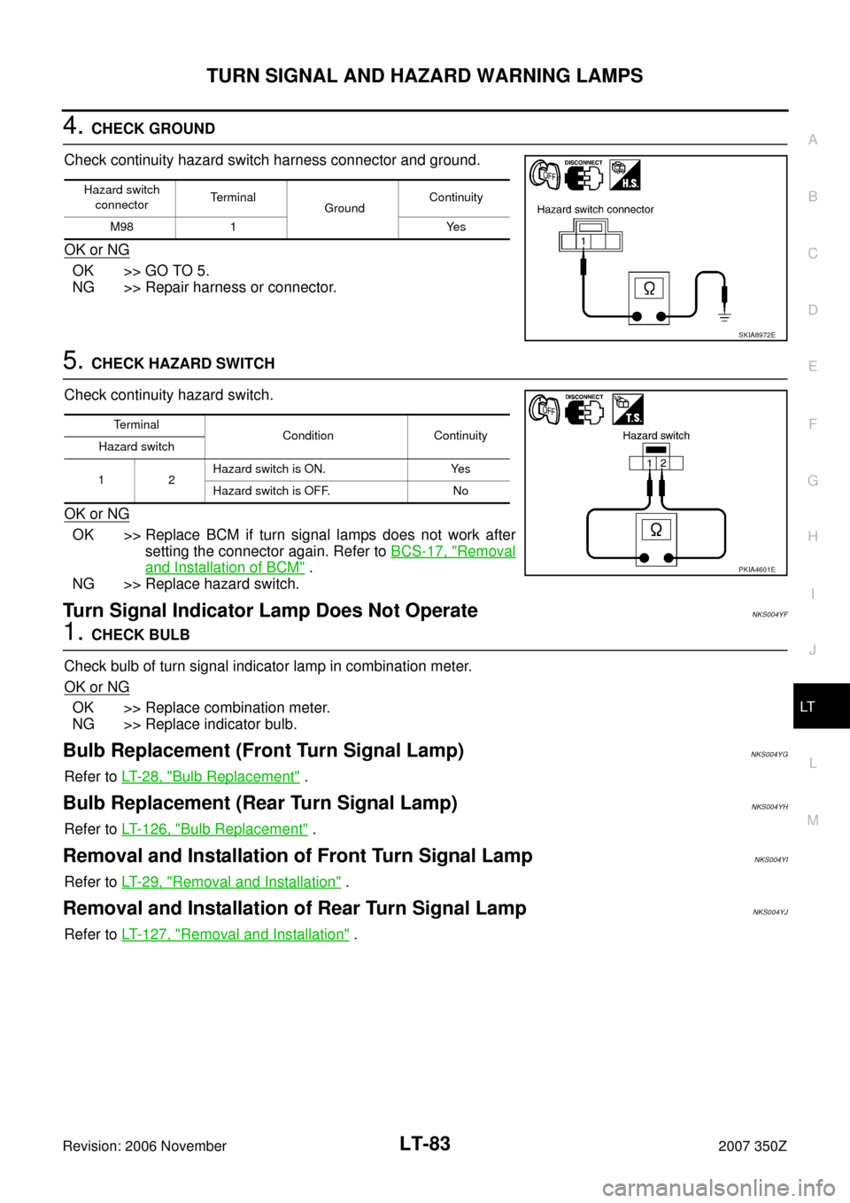
4. CHECK GROUND
Check continuity hazard switch harness connector and ground.
OK or NG
OK >> GO TO 5.
NG >> Repair harness or connector.
5. CHECK HAZARD SWITCH
Check continuity hazard switch.
OK or NG
OK >> Replace BCM if turn signal lamps does not work after
setting the connector again. Refer to BCS-17, "
Removal
and Installation of BCM" .
NG >> Replace hazard switch.
Turn Signal Indicator Lamp Does Not OperateNKS004YF
1. CHECK BULB
Check bulb of turn signal indicator lamp in combination meter.
OK or NG
OK >> Replace combination meter.
NG >> Replace indicator bulb.
Bulb Replacement (Front Turn Signal Lamp)NKS004YG
Refer to LT- 2 8 , "Bulb Replacement" .
Bulb Replacement (Rear Turn Signal Lamp)NKS004YH
Refer to LT- 1 2 6 , "Bulb Replacement" .
Removal and Installation of Front Turn Signal LampNKS004YI
Refer to LT- 2 9 , "Removal and Installation" .
Removal and Installation of Rear Turn Signal Lamp NKS004YJ
Refer to LT- 1 2 7 , "Removal and Installation" .
Hazard switch
connectorTerminal
Ground Continuity
M98 1 Yes
SKIA8972E
Terminal
Condition Continuity
Hazard switch
12Hazard switch is ON. Yes
Hazard switch is OFF. No
PKIA4601E
Page 84 of 172
LT-84
LIGHTING AND TURN SIGNAL SWITCH
Revision: 2006 November2007 350Z
LIGHTING AND TURN SIGNAL SWITCHPFP:25540
Removal and InstallationNKS004YK
REMOVAL
1. Remove steering column lower cover. Refer to IP-10, "INSTRU-
MENT PANEL ASSEMBLY" .
2. Remove column upper cover and combination meter assembly.
Refer to IP-10, "
INSTRUMENT PANEL ASSEMBLY" .
3. While pressing pawls in direction as shown in the figure, pull
lighting and turn signal switch toward driver door and disconnect
from the base.
INSTALLATION
Installation is the reverse order of removal.
PKIB4968E
Page 87 of 172
COMBINATION SWITCH
LT-87
C
D
E
F
G
H
I
J
L
MA
B
LT
Revision: 2006 November2007 350Z
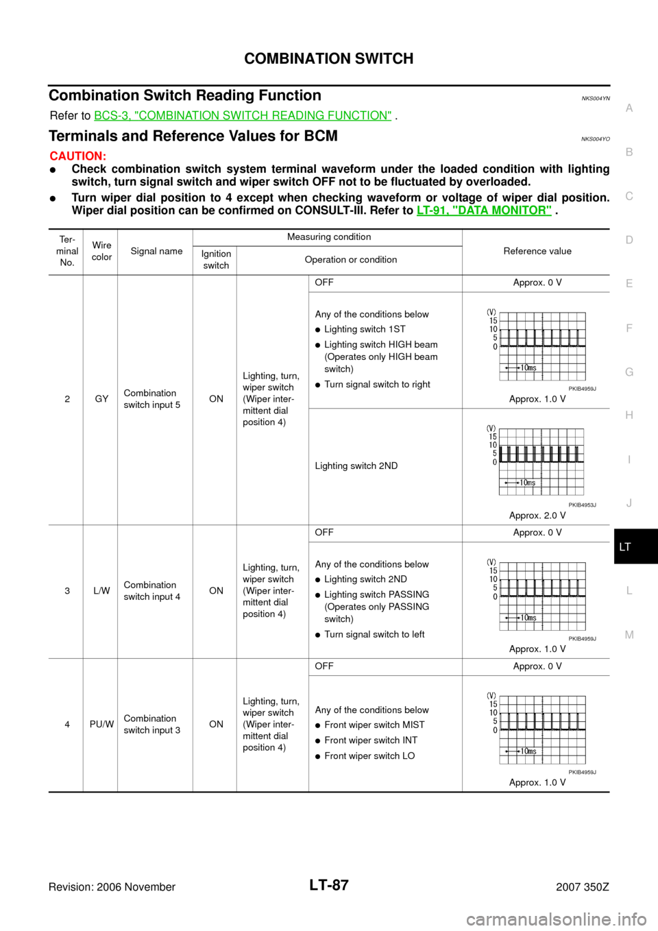
Combination Switch Reading FunctionNKS004YN
Refer to BCS-3, "COMBINATION SWITCH READING FUNCTION" .
Terminals and Reference Values for BCMNKS004YO
CAUTION:
�Check combination switch system terminal waveform under the loaded condition with lighting
switch, turn signal switch and wiper switch OFF not to be fluctuated by overloaded.
�Turn wiper dial position to 4 except when checking waveform or voltage of wiper dial position.
Wiper dial position can be confirmed on CONSULT-III. Refer to LT- 9 1 , "
DATA MONITOR" .
Te r -
minal
No.Wire
colorSignal nameMeasuring condition
Reference value
Ignition
switchOperation or condition
2GYCombination
switch input 5ONLighting, turn,
wiper switch
(Wiper inter-
mittent dial
position 4)OFF Approx. 0 V
Any of the conditions below
�Lighting switch 1ST
�Lighting switch HIGH beam
(Operates only HIGH beam
switch)
�Turn signal switch to right
Approx. 1.0 V
Lighting switch 2ND
Approx. 2.0 V
3L/WCombination
switch input 4ONLighting, turn,
wiper switch
(Wiper inter-
mittent dial
position 4)OFF Approx. 0 V
Any of the conditions below
�Lighting switch 2ND
�Lighting switch PASSING
(Operates only PASSING
switch)
�Turn signal switch to left
Approx. 1.0 V
4PU/WCombination
switch input 3ONLighting, turn,
wiper switch
(Wiper inter-
mittent dial
position 4)OFF Approx. 0 V
Any of the conditions below
�Front wiper switch MIST
�Front wiper switch INT
�Front wiper switch LO
Approx. 1.0 V
PKIB4959J
PKIB4953J
PKIB4959J
PKIB4959J