Page 33 of 82
POWER WINDOW SYSTEM
GW-33
C
D
E
F
G
H
J
K
L
MA
B
GW
Revision: 2006 November2007 350Z
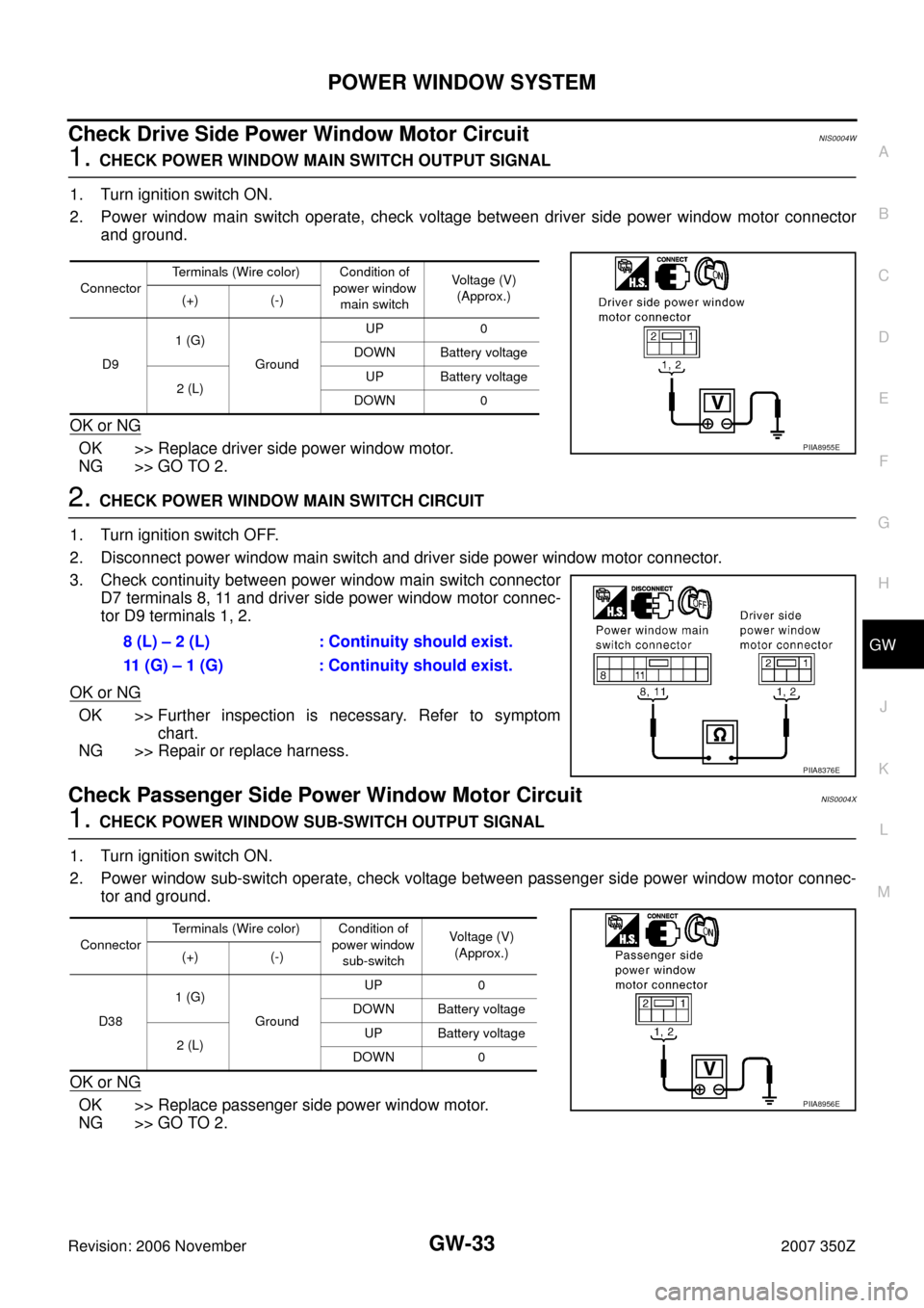
Check Drive Side Power Window Motor CircuitNIS0004W
1. CHECK POWER WINDOW MAIN SWITCH OUTPUT SIGNAL
1. Turn ignition switch ON.
2. Power window main switch operate, check voltage between driver side power window motor connector
and ground.
OK or NG
OK >> Replace driver side power window motor.
NG >> GO TO 2.
2. CHECK POWER WINDOW MAIN SWITCH CIRCUIT
1. Turn ignition switch OFF.
2. Disconnect power window main switch and driver side power window motor connector.
3. Check continuity between power window main switch connector
D7 terminals 8, 11 and driver side power window motor connec-
tor D9 terminals 1, 2.
OK or NG
OK >> Further inspection is necessary. Refer to symptom
chart.
NG >> Repair or replace harness.
Check Passenger Side Power Window Motor CircuitNIS0004X
1. CHECK POWER WINDOW SUB-SWITCH OUTPUT SIGNAL
1. Turn ignition switch ON.
2. Power window sub-switch operate, check voltage between passenger side power window motor connec-
tor and ground.
OK or NG
OK >> Replace passenger side power window motor.
NG >> GO TO 2.
ConnectorTerminals (Wire color) Condition of
power window
main switchVoltage (V)
(Approx.)
(+) (-)
D91 (G)
GroundUP 0
DOWN Battery voltage
2 (L)UP Battery voltage
DOWN 0
PIIA8955E
8 (L) – 2 (L) : Continuity should exist.
11 (G) – 1 (G) : Continuity should exist.
PIIA8376E
ConnectorTerminals (Wire color) Condition of
power window
sub-switchVoltage (V)
(Approx.)
(+) (-)
D381 (G)
GroundUP 0
DOWN Battery voltage
2 (L)UP Battery voltage
DOWN 0
PIIA8956E
Page 34 of 82
GW-34
POWER WINDOW SYSTEM
Revision: 2006 November2007 350Z
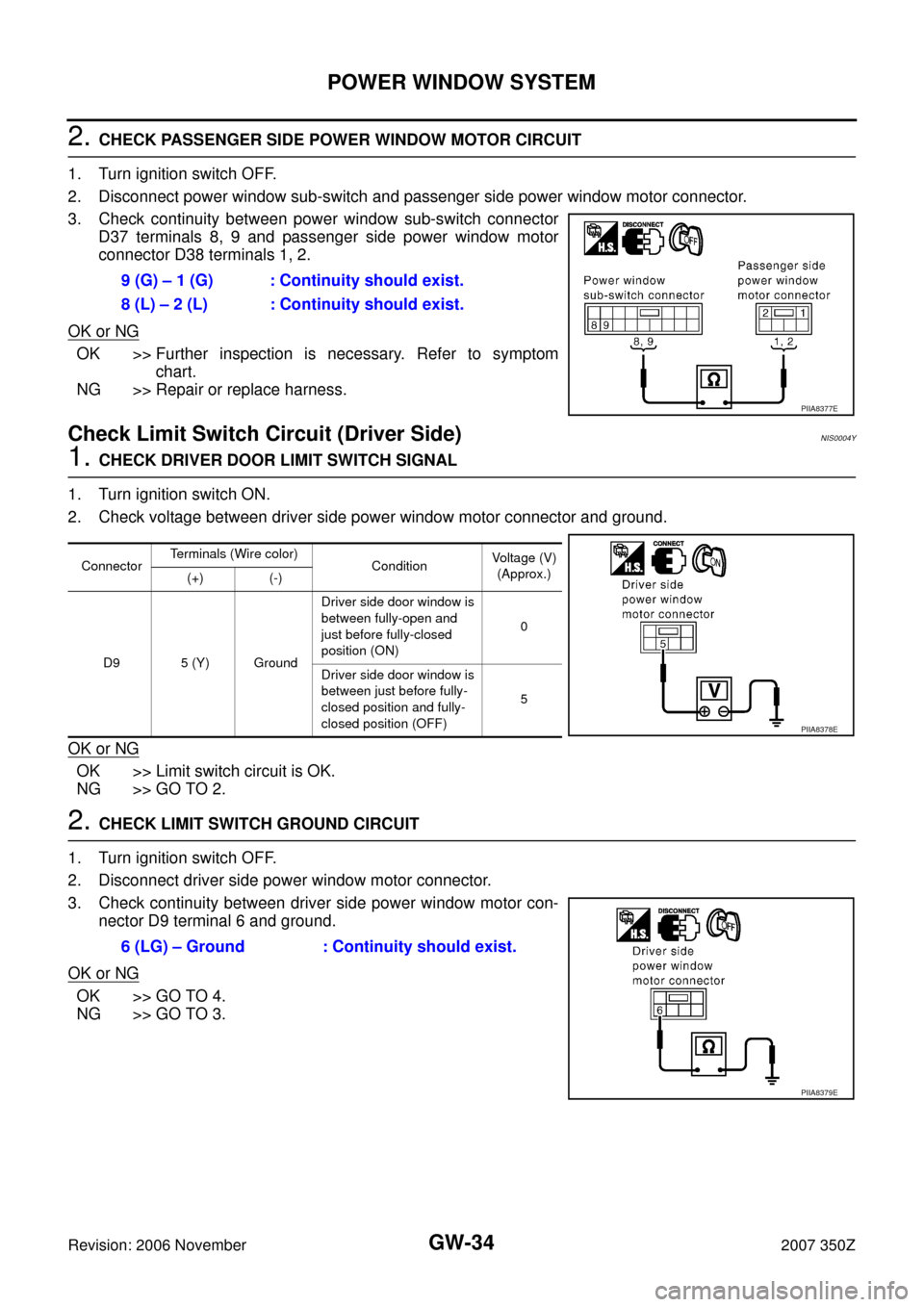
2. CHECK PASSENGER SIDE POWER WINDOW MOTOR CIRCUIT
1. Turn ignition switch OFF.
2. Disconnect power window sub-switch and passenger side power window motor connector.
3. Check continuity between power window sub-switch connector
D37 terminals 8, 9 and passenger side power window motor
connector D38 terminals 1, 2.
OK or NG
OK >> Further inspection is necessary. Refer to symptom
chart.
NG >> Repair or replace harness.
Check Limit Switch Circuit (Driver Side)NIS0004Y
1. CHECK DRIVER DOOR LIMIT SWITCH SIGNAL
1. Turn ignition switch ON.
2. Check voltage between driver side power window motor connector and ground.
OK or NG
OK >> Limit switch circuit is OK.
NG >> GO TO 2.
2. CHECK LIMIT SWITCH GROUND CIRCUIT
1. Turn ignition switch OFF.
2. Disconnect driver side power window motor connector.
3. Check continuity between driver side power window motor con-
nector D9 terminal 6 and ground.
OK or NG
OK >> GO TO 4.
NG >> GO TO 3.9 (G) – 1 (G) : Continuity should exist.
8 (L) – 2 (L) : Continuity should exist.
PIIA8377E
ConnectorTerminals (Wire color)
Condition Voltage (V)
(Approx.)
(+) (-)
D9 5 (Y) GroundDriver side door window is
between fully-open and
just before fully-closed
position (ON)0
Driver side door window is
between just before fully-
closed position and fully-
closed position (OFF)5
PIIA8378E
6 (LG) – Ground : Continuity should exist.
PIIA8379E
Page 35 of 82
POWER WINDOW SYSTEM
GW-35
C
D
E
F
G
H
J
K
L
MA
B
GW
Revision: 2006 November2007 350Z
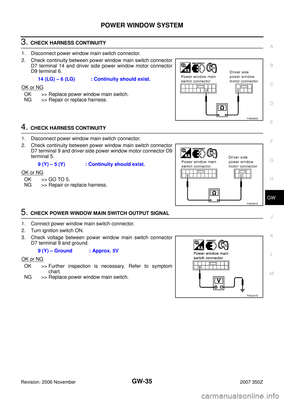
3. CHECK HARNESS CONTINUITY
1. Disconnect power window main switch connector.
2. Check continuity between power window main switch connector
D7 terminal 14 and driver side power window motor connector
D9 terminal 6.
OK or NG
OK >> Replace power window main switch.
NG >> Repair or replace harness.
4. CHECK HARNESS CONTINUITY
1. Disconnect power window main switch connector.
2. Check continuity between power window main switch connector
D7 terminal 9 and driver side power window motor connector D9
terminal 5.
OK or NG
OK >> GO TO 5.
NG >> Repair or replace harness.
5. CHECK POWER WINDOW MAIN SWITCH OUTPUT SIGNAL
1. Connect power window main switch connector.
2. Turn ignition switch ON.
3. Check voltage between power window main switch connector
D7 terminal 9 and ground.
OK or NG
OK >> Further inspection is necessary. Refer to symptom
chart.
NG >> Replace power window main switch.14 (LG) – 6 (LG) : Continuity should exist.
PIIA8380E
9 (Y) – 5 (Y) : Continuity should exist.
PIIA8381E
9 (Y) – Ground : Approx. 5V
PIIA2447E
Page 36 of 82
GW-36
POWER WINDOW SYSTEM
Revision: 2006 November2007 350Z
Check Limit Switch Circuit (Passenger Side)NIS0004Z
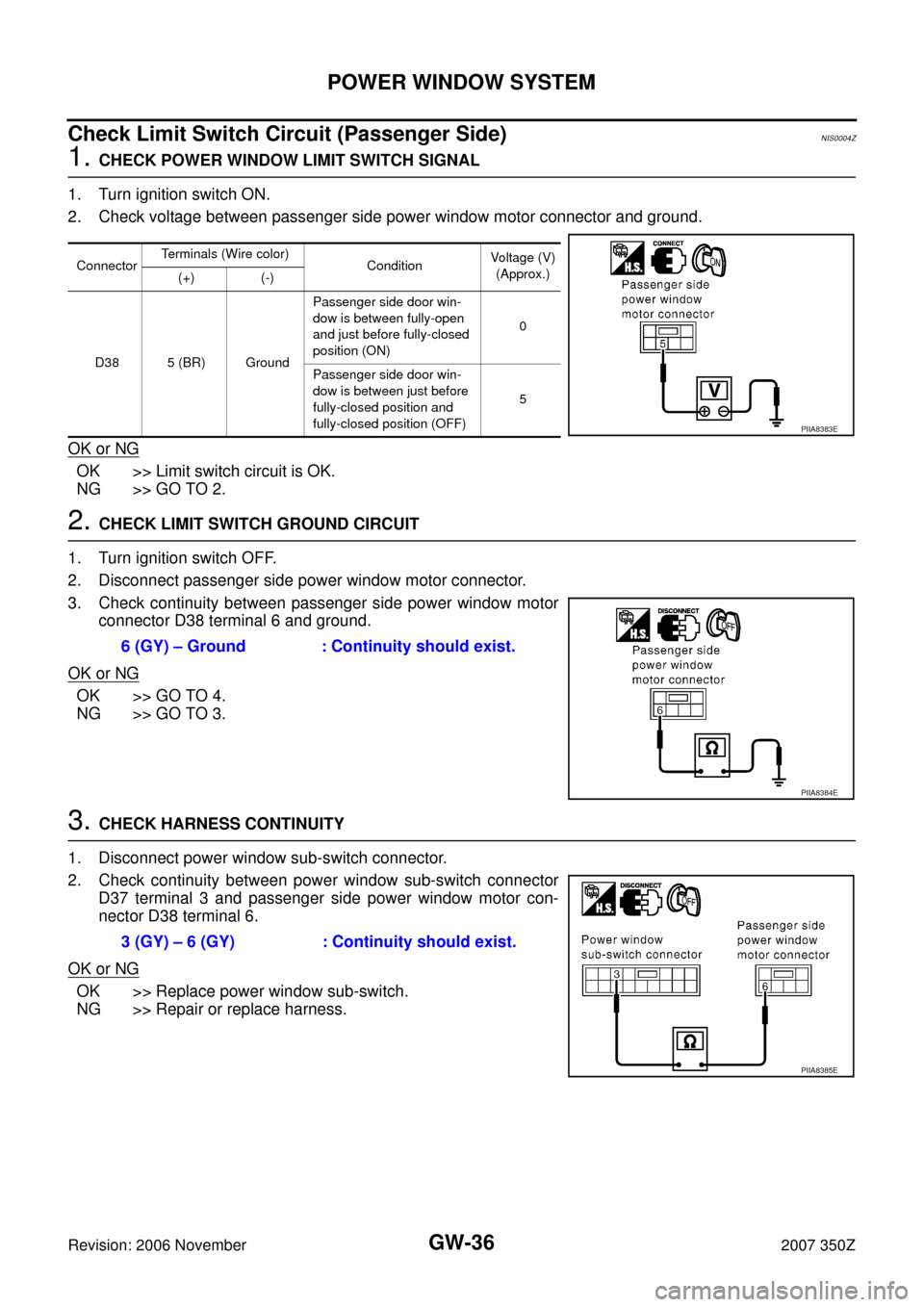
1. CHECK POWER WINDOW LIMIT SWITCH SIGNAL
1. Turn ignition switch ON.
2. Check voltage between passenger side power window motor connector and ground.
OK or NG
OK >> Limit switch circuit is OK.
NG >> GO TO 2.
2. CHECK LIMIT SWITCH GROUND CIRCUIT
1. Turn ignition switch OFF.
2. Disconnect passenger side power window motor connector.
3. Check continuity between passenger side power window motor
connector D38 terminal 6 and ground.
OK or NG
OK >> GO TO 4.
NG >> GO TO 3.
3. CHECK HARNESS CONTINUITY
1. Disconnect power window sub-switch connector.
2. Check continuity between power window sub-switch connector
D37 terminal 3 and passenger side power window motor con-
nector D38 terminal 6.
OK or NG
OK >> Replace power window sub-switch.
NG >> Repair or replace harness.
ConnectorTerminals (Wire color)
Condition Voltage (V)
(Approx.)
(+) (-)
D38 5 (BR) GroundPassenger side door win-
dow is between fully-open
and just before fully-closed
position (ON)0
Passenger side door win-
dow is between just before
fully-closed position and
fully-closed position (OFF)5
PIIA8383E
6 (GY) – Ground : Continuity should exist.
PIIA8384E
3 (GY) – 6 (GY) : Continuity should exist.
PIIA8385E
Page 37 of 82
POWER WINDOW SYSTEM
GW-37
C
D
E
F
G
H
J
K
L
MA
B
GW
Revision: 2006 November2007 350Z
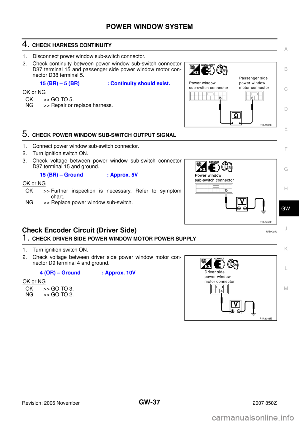
4. CHECK HARNESS CONTINUITY
1. Disconnect power window sub-switch connector.
2. Check continuity between power window sub-switch connector
D37 terminal 15 and passenger side power window motor con-
nector D38 terminal 5.
OK or NG
OK >> GO TO 5.
NG >> Repair or replace harness.
5. CHECK POWER WINDOW SUB-SWITCH OUTPUT SIGNAL
1. Connect power window sub-switch connector.
2. Turn ignition switch ON.
3. Check voltage between power window sub-switch connector
D37 terminal 15 and ground.
OK or NG
OK >> Further inspection is necessary. Refer to symptom
chart.
NG >> Replace power window sub-switch.
Check Encoder Circuit (Driver Side)NIS00050
1. CHECK DRIVER SIDE POWER WINDOW MOTOR POWER SUPPLY
1. Turn ignition switch ON.
2. Check voltage between driver side power window motor con-
nector D9 terminal 4 and ground.
OK or NG
OK >> GO TO 3.
NG >> GO TO 2.15 (BR) – 5 (BR) : Continuity should exist.
PIIA8386E
15 (BR) – Ground : Approx. 5V
PIIA2452E
4 (OR) – Ground : Approx. 10V
PIIA8388E
Page 38 of 82
GW-38
POWER WINDOW SYSTEM
Revision: 2006 November2007 350Z
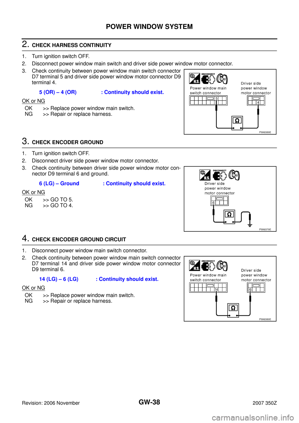
2. CHECK HARNESS CONTINUITY
1. Turn ignition switch OFF.
2. Disconnect power window main switch and driver side power window motor connector.
3. Check continuity between power window main switch connector
D7 terminal 5 and driver side power window motor connector D9
terminal 4.
OK or NG
OK >> Replace power window main switch.
NG >> Repair or replace harness.
3. CHECK ENCODER GROUND
1. Turn ignition switch OFF.
2. Disconnect driver side power window motor connector.
3. Check continuity between driver side power window motor con-
nector D9 terminal 6 and ground.
OK or NG
OK >> GO TO 5.
NG >> GO TO 4.
4. CHECK ENCODER GROUND CIRCUIT
1. Disconnect power window main switch connector.
2. Check continuity between power window main switch connector
D7 terminal 14 and driver side power window motor connector
D9 terminal 6.
OK or NG
OK >> Replace power window main switch.
NG >> Repair or replace harness.5 (OR) – 4 (OR) : Continuity should exist.
PIIA8389E
6 (LG) – Ground : Continuity should exist.
PIIA8379E
14 (LG) – 6 (LG) : Continuity should exist.
PIIA8380E
Page 39 of 82
POWER WINDOW SYSTEM
GW-39
C
D
E
F
G
H
J
K
L
MA
B
GW
Revision: 2006 November2007 350Z
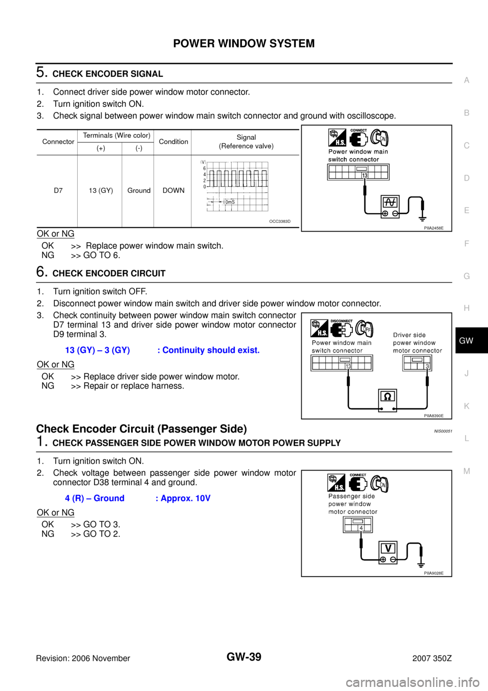
5. CHECK ENCODER SIGNAL
1. Connect driver side power window motor connector.
2. Turn ignition switch ON.
3. Check signal between power window main switch connector and ground with oscilloscope.
OK or NG
OK >> Replace power window main switch.
NG >> GO TO 6.
6. CHECK ENCODER CIRCUIT
1. Turn ignition switch OFF.
2. Disconnect power window main switch and driver side power window motor connector.
3. Check continuity between power window main switch connector
D7 terminal 13 and driver side power window motor connector
D9 terminal 3.
OK or NG
OK >> Replace driver side power window motor.
NG >> Repair or replace harness.
Check Encoder Circuit (Passenger Side)NIS00051
1. CHECK PASSENGER SIDE POWER WINDOW MOTOR POWER SUPPLY
1. Turn ignition switch ON.
2. Check voltage between passenger side power window motor
connector D38 terminal 4 and ground.
OK or NG
OK >> GO TO 3.
NG >> GO TO 2.
ConnectorTerminals (Wire color)
ConditionSignal
(Reference valve)
(+) (-)
D7 13 (GY) Ground DOWN
PIIA2458EOCC3383D
13 (GY) – 3 (GY) : Continuity should exist.
PIIA8390E
4 (R) – Ground : Approx. 10V
PIIA9028E
Page 40 of 82
GW-40
POWER WINDOW SYSTEM
Revision: 2006 November2007 350Z
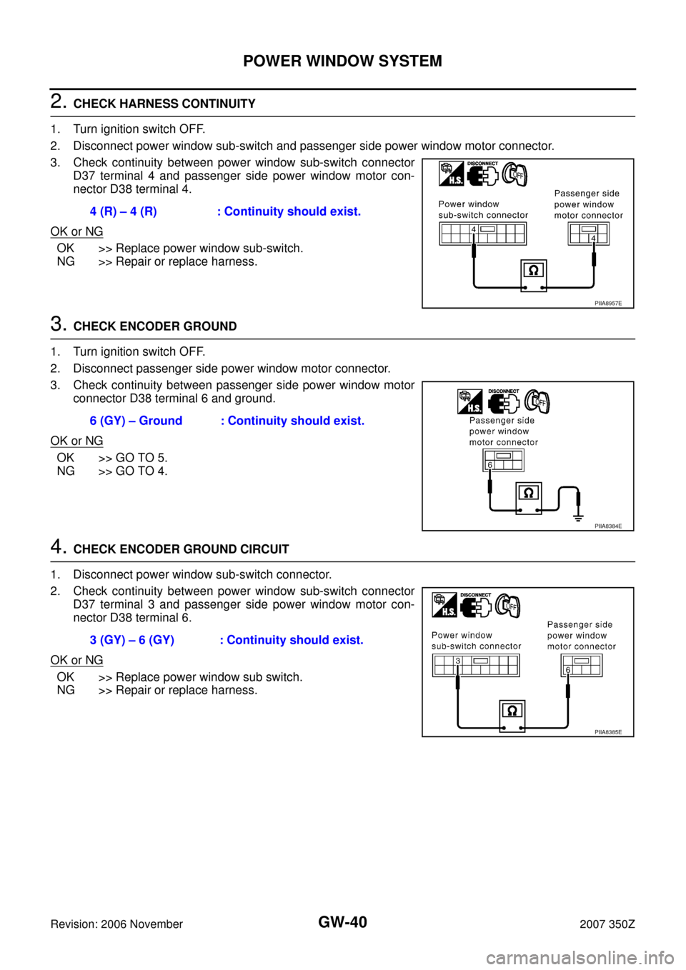
2. CHECK HARNESS CONTINUITY
1. Turn ignition switch OFF.
2. Disconnect power window sub-switch and passenger side power window motor connector.
3. Check continuity between power window sub-switch connector
D37 terminal 4 and passenger side power window motor con-
nector D38 terminal 4.
OK or NG
OK >> Replace power window sub-switch.
NG >> Repair or replace harness.
3. CHECK ENCODER GROUND
1. Turn ignition switch OFF.
2. Disconnect passenger side power window motor connector.
3. Check continuity between passenger side power window motor
connector D38 terminal 6 and ground.
OK or NG
OK >> GO TO 5.
NG >> GO TO 4.
4. CHECK ENCODER GROUND CIRCUIT
1. Disconnect power window sub-switch connector.
2. Check continuity between power window sub-switch connector
D37 terminal 3 and passenger side power window motor con-
nector D38 terminal 6.
OK or NG
OK >> Replace power window sub switch.
NG >> Repair or replace harness.4 (R) – 4 (R) : Continuity should exist.
PIIA8957E
6 (GY) – Ground : Continuity should exist.
PIIA8384E
3 (GY) – 6 (GY) : Continuity should exist.
PIIA8385E