Page 74 of 82

GW-74
REAR WINDOW DEFOGGER
Revision: 2006 November2007 350Z
Check Rear Window Defogger Circuit / For RoadsterNIS0005V
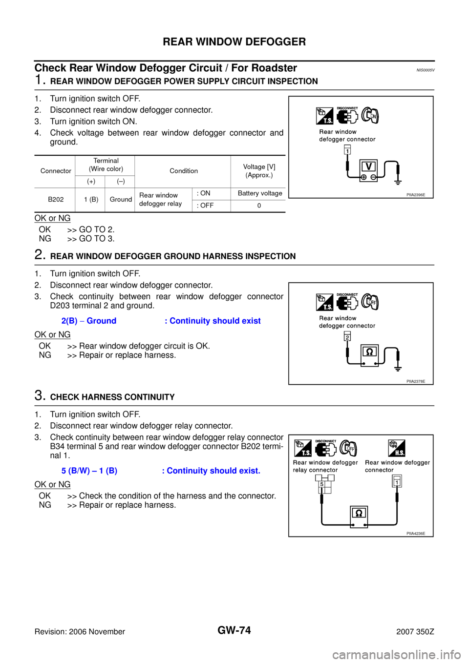
1. REAR WINDOW DEFOGGER POWER SUPPLY CIRCUIT INSPECTION
1. Turn ignition switch OFF.
2. Disconnect rear window defogger connector.
3. Turn ignition switch ON.
4. Check voltage between rear window defogger connector and
ground.
OK or NG
OK >> GO TO 2.
NG >> GO TO 3.
2. REAR WINDOW DEFOGGER GROUND HARNESS INSPECTION
1. Turn ignition switch OFF.
2. Disconnect rear window defogger connector.
3. Check continuity between rear window defogger connector
D203 terminal 2 and ground.
OK or NG
OK >> Rear window defogger circuit is OK.
NG >> Repair or replace harness.
3. CHECK HARNESS CONTINUITY
1. Turn ignition switch OFF.
2. Disconnect rear window defogger relay connector.
3. Check continuity between rear window defogger relay connector
B34 terminal 5 and rear window defogger connector B202 termi-
nal 1.
OK or NG
OK >> Check the condition of the harness and the connector.
NG >> Repair or replace harness.
ConnectorTerminal
(Wire color)
ConditionVoltage [V]
(Approx.)
(+) (–)
B202 1 (B) GroundRear window
defogger relay: ON Battery voltage
: OFF 0
PIIA2396E
2(B) − Ground : Continuity should exist
PIIA2378E
5 (B/W) – 1 (B) : Continuity should exist.
PIIA4236E
Page 75 of 82

REAR WINDOW DEFOGGER
GW-75
C
D
E
F
G
H
J
K
L
MA
B
GW
Revision: 2006 November2007 350Z
Check Door Mirror Defogger Power Supply CircuitNIS0005W
1. CHECK FUSE
�Check 10A fuse [No. 8, located in fuse block (J/B)].
NOTE:
Refer to GW-56, "
Component Parts and Harness Connector Location" .
OK or NG
OK >> GO TO 2.
NG >> If fuse is blown, be sure to eliminate cause of malfunction before installing new fuse, refer to PG-
4, "POWER SUPPLY ROUTING CIRCUIT" .
2. DOOR MIRROR DEFOGGER POWER SUPPLY CIRCUIT INSPECTION 1
1. Turn ignition switch ON.
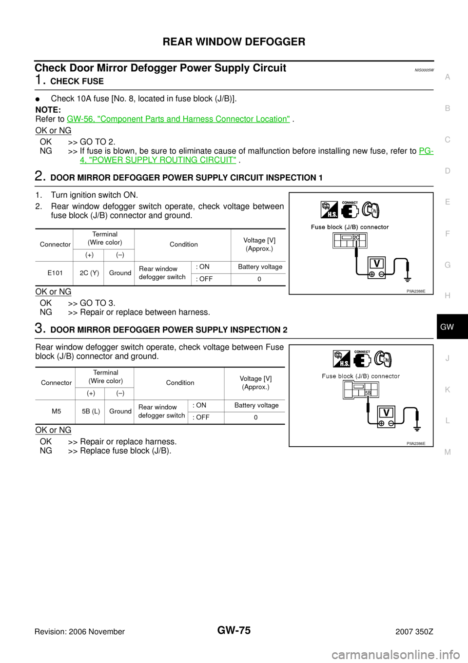
2. Rear window defogger switch operate, check voltage between
fuse block (J/B) connector and ground.
OK or NG
OK >> GO TO 3.
NG >> Repair or replace between harness.
3. DOOR MIRROR DEFOGGER POWER SUPPLY INSPECTION 2
Rear window defogger switch operate, check voltage between Fuse
block (J/B) connector and ground.
OK or NG
OK >> Repair or replace harness.
NG >> Replace fuse block (J/B).
ConnectorTerminal
(Wire color)
ConditionVoltage [V]
(Approx.)
(+) (–)
E101 2C (Y) GroundRear window
defogger switch: ON Battery voltage
: OFF 0
PIIA2388E
ConnectorTerminal
(Wire color)
ConditionVoltage [V]
(Approx.)
(+) (–)
M5 5B (L) GroundRear window
defogger switch: ON Battery voltage
: OFF 0
PIIA2386E
Page 76 of 82

GW-76
REAR WINDOW DEFOGGER
Revision: 2006 November2007 350Z
Check Driver Side Door Mirror Defogger CircuitNIS0005X
1. DOOR MIRROR DEFOGGER POWER SUPPLY CIRCUIT INSPECTION
1. Turn ignition switch OFF.
2. Disconnect driver side door mirror defogger connector.
3. Turn ignition switch ON.
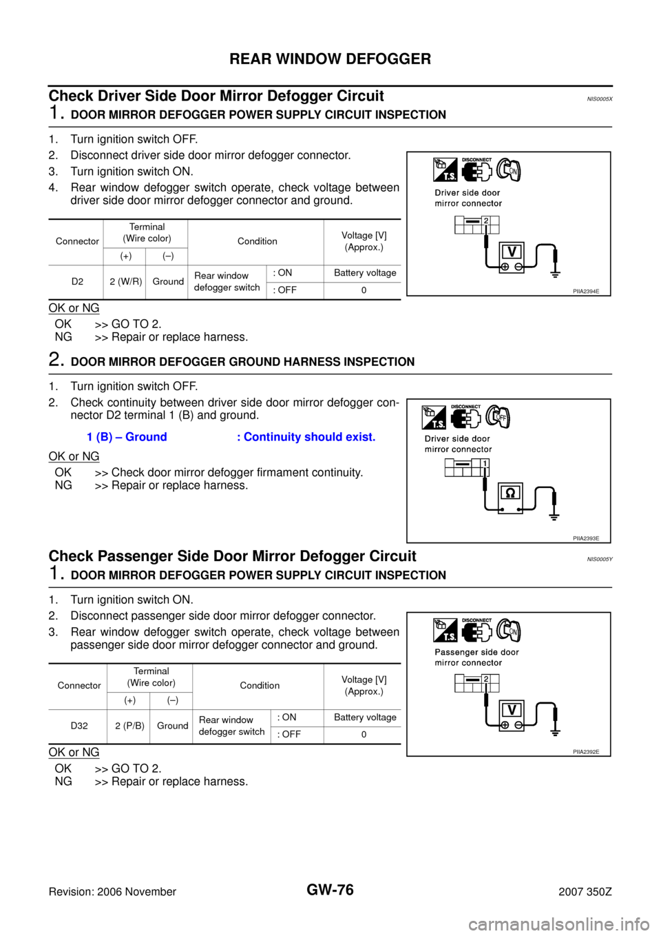
4. Rear window defogger switch operate, check voltage between
driver side door mirror defogger connector and ground.
OK or NG
OK >> GO TO 2.
NG >> Repair or replace harness.
2. DOOR MIRROR DEFOGGER GROUND HARNESS INSPECTION
1. Turn ignition switch OFF.
2. Check continuity between driver side door mirror defogger con-
nector D2 terminal 1 (B) and ground.
OK or NG
OK >> Check door mirror defogger firmament continuity.
NG >> Repair or replace harness.
Check Passenger Side Door Mirror Defogger Circuit NIS0005Y
1. DOOR MIRROR DEFOGGER POWER SUPPLY CIRCUIT INSPECTION
1. Turn ignition switch ON.
2. Disconnect passenger side door mirror defogger connector.
3. Rear window defogger switch operate, check voltage between
passenger side door mirror defogger connector and ground.
OK or NG
OK >> GO TO 2.
NG >> Repair or replace harness.
ConnectorTerminal
(Wire color)
ConditionVoltage [V]
(Approx.)
(+) (–)
D2 2 (W/R) GroundRear window
defogger switch: ON Battery voltage
: OFF 0
PIIA2394E
1 (B) – Ground : Continuity should exist.
PIIA2393E
ConnectorTerminal
(Wire color)
ConditionVoltage [V]
(Approx.)
(+) (–)
D32 2 (P/B) GroundRear window
defogger switch: ON Battery voltage
: OFF 0
PIIA2392E
Page 78 of 82
GW-78
REAR WINDOW DEFOGGER
Revision: 2006 November2007 350Z
Check FilamentNIS0005Z
1. When measuring voltage, wrap tin foil around the top of the neg-
ative probe. Then press the foil against the wire with your finger.
2. Attach probe circuit tester (in Volt range) to middle portion of
each filament.
3. If a filament is burned out, circuit tester registers 0 or battery
voltage.
4. To locate burned out point, move probe to left and right along fil-
ament. Test needle will swing abruptly when probe passes the
point.
SEL122R
SEL263
SEL265
Page:
< prev 1-8 9-16 17-24