Page 9 of 14

OIL FILTER
LU-9
C
D
E
F
G
H
I
J
K
L
MA
LU
Revision: 2006 November2007 350Z
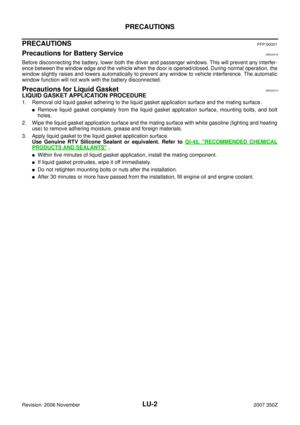
OIL FILTERPFP:15208
Removal and InstallationNBS0001G
REMOVAL
WARNING:
Be careful not to get burned when engine and engine oil may be hot.
CAUTION:
�Oil filter is provided with relief valve. Use Genuine NISSAN Oil Filter or equivalent.
�When removing, prepare a shop cloth to absorb any engine oil leakage or spillage.
�Do not allow engine oil to adhere to drive belts.
�Completely wipe off any engine oil that adheres to engine and vehicle.
1. Remove undercover with power tool.
2. Using oil filter wrench [SST: KV10115801(J38956)] (B), remove
oil filter.
INSTALLATION
1. Remove foreign materials adhering to oil filter installation surface.
2. Apply engine oil to the oil seal contact surface of new oil filter.
3. Screw oil filter manually until it touches the installation surface,
then tighten it by 2/3 turn. Or tighten to specification.
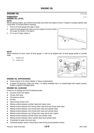
INSPECTION AFTER INSTALLATION
1. Check the engine oil level. Refer to LU-6, "ENGINE OIL" .
2. Start engine, and check there is no leaks of engine oil.
3. Stop engine and wait for 10 minutes.
4. Check the engine oil level and adjust engine oil. Refer to LU-6, "
ENGINE OIL" .
A: 2WD
: Engine front
PBIC4934E
SMA010
Oil filter:
: 17.7 N·m (1.8 kg-m, 13 ft-lb)
SMA229B
Page 10 of 14
 and")
LU-10
OIL PUMP
Revision: 2006 November2007 350Z
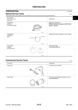
OIL PUMPPFP:15010
Removal and InstallationNBS0001I
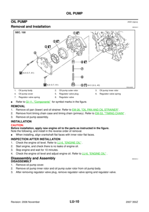
�Refer to GI-11, "Components" for symbol marks in the figure.
REMOVAL
1. Remove oil pan (lower) and oil strainer. Refer to EM-26, "OIL PAN AND OIL STRAINER" .
2. Remove front timing chain case and timing chain (primary). Refer to EM-53, "
TIMING CHAIN" .
3. Remove oil pump assembly.
INSTALLATION
CAUTION:
Before installation, apply new engine oil to the parts as instructed in the figure.
Note the following, and install in the reverse order of removal.
�When installing, align crankshaft flat faces with inner rotor flat faces.
INSPECTION AFTER INSTALLATION
1. Check the engine oil level. Refer to LU-6, "ENGINE OIL" .
2. Start engine, and check there is no leaks of engine oil.
3. Stop engine and wait for 10 minutes.
4. Check the engine oil level and adjust engine oil. Refer to LU-6, "
ENGINE OIL" .
Disassembly and AssemblyNBS0001J
DISASSEMBLY
1. Remove oil pump cover.
2. Remove oil pump inner rotor and oil pump outer rotor from oil pump body.
3. After removing regulator valve plug, remove regulator valve spring and regulator valve.
1. Oil pump body 2. Oil pump outer rotor 3. Oil pump inner rotor
4. Oil pump cover 5. Regulator valve plug 6. Regulator valve spring
7. Regulator valve spring 8. Regulator valve
PBIC4935E
Page 11 of 14

OIL PUMP
LU-11
C
D
E
F
G
H
I
J
K
L
MA
LU
Revision: 2006 November2007 350Z
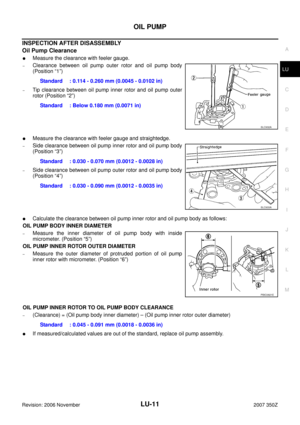
INSPECTION AFTER DISASSEMBLY
Oil Pump Clearance
�Measure the clearance with feeler gauge.
–Clearance between oil pump outer rotor and oil pump body
(Position “1”)
–Tip clearance between oil pump inner rotor and oil pump outer
rotor (Position “2”)
�Measure the clearance with feeler gauge and straightedge.
–Side clearance between oil pump inner rotor and oil pump body
(Position “3”)
–Side clearance between oil pump outer rotor and oil pump body
(Position “4”)
�Calculate the clearance between oil pump inner rotor and oil pump body as follows:
OIL PUMP BODY INNER DIAMETER
–Measure the inner diameter of oil pump body with inside
micrometer. (Position “5”)
OIL PUMP INNER ROTOR OUTER DIAMETER
–Measure the outer diameter of protruded portion of oil pump
inner rotor with micrometer. (Position “6”)
OIL PUMP INNER ROTOR TO OIL PUMP BODY CLEARANCE
–(Clearance) = (Oil pump body inner diameter) – (Oil pump inner rotor outer diameter)
�If measured/calculated values are out of the standard, replace oil pump assembly.Standard : 0.114 - 0.260 mm (0.0045 - 0.0102 in)
Standard : Below 0.180 mm (0.0071 in)
SLC932A
Standard : 0.030 - 0.070 mm (0.0012 - 0.0028 in)
Standard : 0.030 - 0.090 mm (0.0012 - 0.0035 in)
SLC933A
PBIC0821E
Standard : 0.045 - 0.091 mm (0.0018 - 0.0036 in)
Page 12 of 14
LU-12
OIL PUMP
Revision: 2006 November2007 350Z
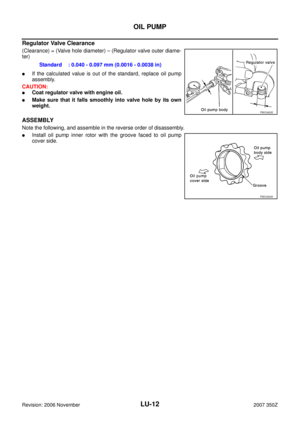
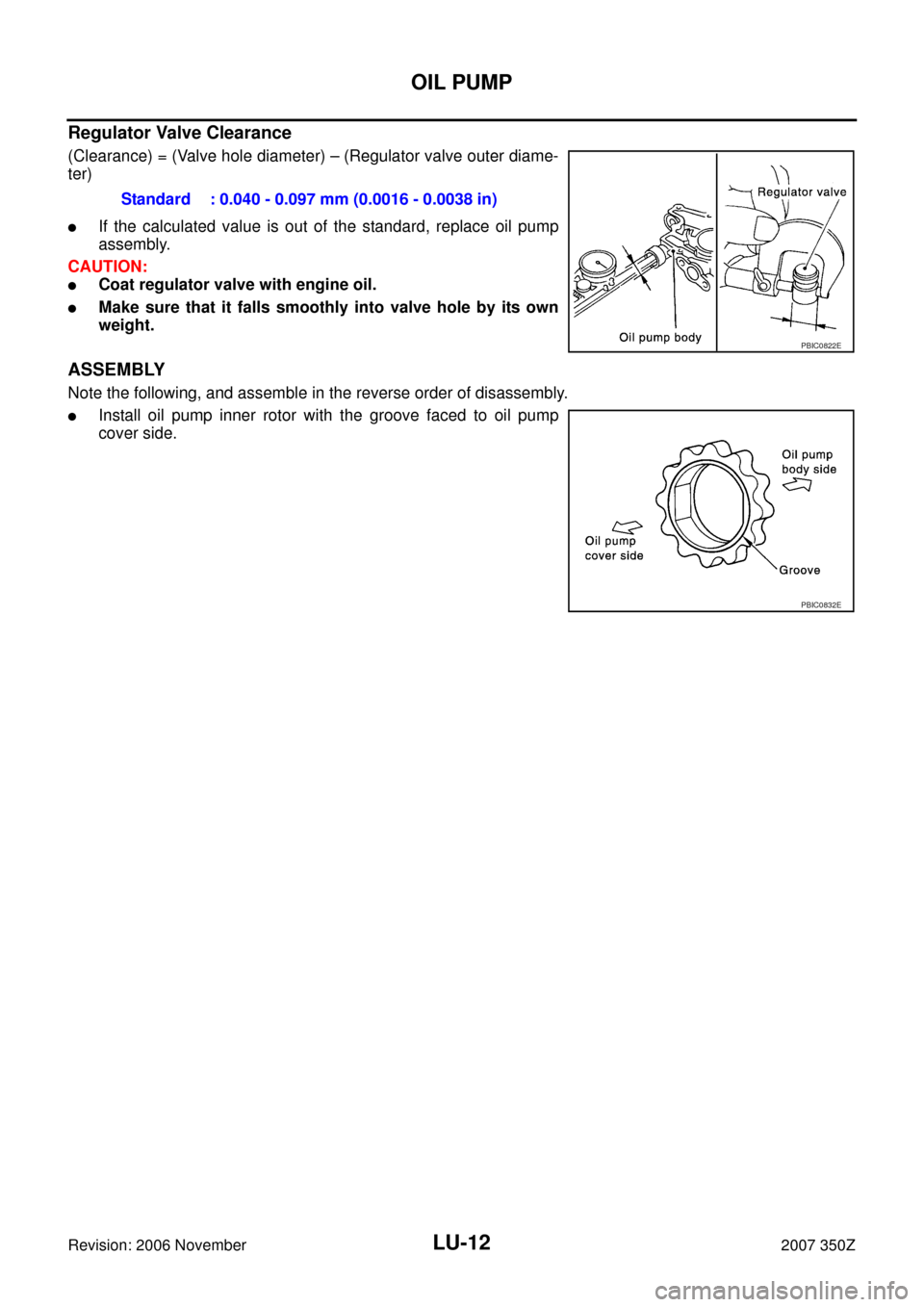
Regulator Valve Clearance
(Clearance) = (Valve hole diameter) – (Regulator valve outer diame-
ter)
�If the calculated value is out of the standard, replace oil pump
assembly.
CAUTION:
�Coat regulator valve with engine oil.
�Make sure that it falls smoothly into valve hole by its own
weight.
ASSEMBLY
Note the following, and assemble in the reverse order of disassembly.
�Install oil pump inner rotor with the groove faced to oil pump
cover side.Standard : 0.040 - 0.097 mm (0.0016 - 0.0038 in)
PBIC0822E
PBIC0832E
Page 13 of 14

LU-13
C
D
E
F
G
H
I
J
K
L
MA
LU
Revision: 2006 November2007 350Z
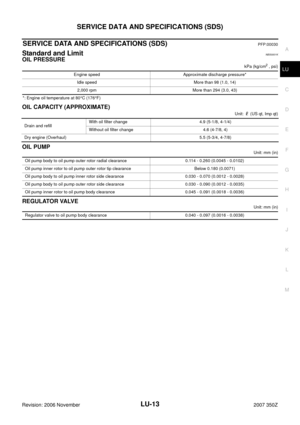
SERVICE DATA AND SPECIFICATIONS (SDS)PFP:00030
Standard and LimitNBS0001K
OIL PRESSURE
kPa (kg/cm")
SERVICE DATA AND SPECIFICATIONS (SDS)
LU-13
C
D
E
F
G
H
I
J
K
L
MA
LU
Revision: 2006 November2007 350Z
SERVICE DATA AND SPECIFICATIONS (SDS)PFP:00030
Standard and LimitNBS0001K
OIL PRESSURE
kPa (kg/cm2 , psi)
*: Engine oil temperature at 80°C (176°F)
OIL CAPACITY (APPROXIMATE)
Unit: (US qt, Imp qt)
OIL PUMP
Unit: mm (in)
REGULATOR VALVE
Unit: mm (in) Engine speed Approximate discharge pressure*
Idle speed More than 98 (1.0, 14)
2,000 rpm More than 294 (3.0, 43)
Drain and refillWith oil filter change 4.9 (5-1/8, 4-1/4)
Without oil filter change 4.6 (4-7/8, 4)
Dry engine (Overhaul) 5.5 (5-3/4, 4-7/8)
Oil pump body to oil pump outer rotor radial clearance 0.114 - 0.260 (0.0045 - 0.0102)
Oil pump inner rotor to oil pump outer rotor tip clearance Below 0.180 (0.0071)
Oil pump body to oil pump inner rotor side clearance 0.030 - 0.070 (0.0012 - 0.0028)
Oil pump body to oil pump outer rotor side clearance 0.030 - 0.090 (0.0012 - 0.0035)
Oil pump inner rotor to oil pump body clearance 0.045 - 0.091 (0.0018 - 0.0036)
Regulator valve to oil pump body clearance 0.040 - 0.097 (0.0016 - 0.0038)
Page 14 of 14
LU-14
SERVICE DATA AND SPECIFICATIONS (SDS)
Revision: 2006 November2007 350Z


Revision: 2006 November2007 350Z")