Page 24 of 30
![NISSAN 350Z 2007 Z33 Engine Cooling System Workshop Manual CO-24
WATER PUMP
Revision: 2006 November2007 350Z
b. Screw M8 bolts (A) [pitch: 1.25 mm (0.049 in) length: approx. 50
mm (1.97 in)] into water pumps upper and lower mounting bolt
holes until they reac](/manual-img/5/763/w960_763-23.png "NISSAN 350Z 2007 Z33 Engine Cooling System Workshop Manual CO-24
WATER PUMP
Revision: 2006 November2007 350Z
b. Screw M8 bolts (A) [pitch: 1.25 mm (0.049 in) length: approx. 50
mm (1.97 in)] into water pumps upper and lower mounting bolt
holes until they reac")
CO-24
WATER PUMP
Revision: 2006 November2007 350Z
b. Screw M8 bolts (A) [pitch: 1.25 mm (0.049 in) length: approx. 50
mm (1.97 in)] into water pumps upper and lower mounting bolt
holes until they reach timing chain case. Then, alternately
tighten each bolt for a half turn, and pull out water pump (1).
CAUTION:
�Pull straight out while preventing vane from contacting
socket in installation area.
�Remove water pump without causing sprocket to contact
timing chain.
c. Remove M8 bolts and O-rings from water pump (1).
CAUTION:
Do not disassemble water pump.
INSPECTION AFTER REMOVAL
�Check for badly rusted or corroded water pump body assembly.
�Check for rough operation due to excessive end play.
�Replace water pump, if necessary.
INSTALLATION
1. Install new O-rings to water pump.
�Apply engine oil to O-rings (1) and engine coolant to O-ring
(3) as shown in the figure.
�Locate O-ring (1) with yellow paint mark (A) to engine front
side.
�Locate O-ring (3) with light blue paint mark (B) to rear side.
2. Install water pump.
CAUTION:
Do not allow cylinder block to nip O-rings when installing water pump.
�Make sure that timing chain and water pump sprocket are engaged.
�Insert water pump by tightening mounting bolts alternately and evenly.
3. Install timing chain tensioner (primary) as follows:
a. Turn crankshaft clockwise so that timing chain on the timing chain tensioner (primary) side is loose.
PBIC4939E
SLC943A
2 : Water pump
PBIC5074E
Page 25 of 30
 so as to
remove plunger stopper tab from the ratchet of plunger.
NOT")
WATER PUMP
CO-25
C
D
E
F
G
H
I
J
K
L
MA
CO
Revision: 2006 November2007 350Z
b. Pull plunger stopper tab up (or turn lever downward) so as to
remove plunger stopper tab from the ratchet of plunger.
NOTE:
Plunger stopper tab and lever are synchronized.
c. Push plunger into the inside of tensioner body.
d. Hold plunger in the fully compressed position by engaging
plunger stopper tab with the tip of ratchet.
e. To secure lever, insert stopper pin through hole of lever into ten-
sioner body hole.
�The lever parts and the tab are synchronized. Therefore, the
plunger will be secured under this condition.
NOTE:
Figure shows the example of 1.2 mm (0.047 in) diameter thin screwdriver being used as the stopper pin.
f. Install timing chain tensioner (primary).
�Remove dust and foreign material completely from backside of timing chain tensioner (primary) and
from installation area of rear timing chain case.
g. Remove stopper pin.
h. Make sure again that timing chain and water pump sprocket are engaged.
4. Install in the reverse order of removal after this step.
�After starting engine, let idle for three minutes, then rev engine up to 3,000 rpm under no load to
purge air from the high-pressure chamber of chain tensioner. Engine may produce a rattling
noise. This indicates that air still remains in the chamber and is not a matter of concern.
INSPECTION AFTER INSTALLATION
�Check for leaks of engine coolant using radiator cap tester adapter (commercial service tool) and radiator
cap tester (commercial service tool). Refer to CO-10, "
LEAK CHECK" .
�Start and warm up engine. Visually make sure that there is no leaks of engine coolant.
PBIC3568E
Page 26 of 30

CO-26
WATER INLET AND THERMOSTAT ASSEMBLY
Revision: 2006 November2007 350Z
WATER INLET AND THERMOSTAT ASSEMBLYPFP:21200
Removal and InstallationNBS00023
�Refer to GI-11, "Components" for symbol marks in the figure.
REMOVAL
1. Remove undercover with power tool.
2. Drain engine coolant from radiator drain plug at the bottom of radiator. Refer to CO-10, "
Changing Engine
Coolant" .
CAUTION:
�Perform this step when engine is cold.
�Do not spill engine coolant on drive belts.
3. Remove air duct and air cleaner case (LH). Refer to EM-15, "
AIR CLEANER AND AIR DUCT" .
4. Disconnect radiator hose (lower) from water inlet and thermostat assembly.
5. Remove intake valve timing control solenoid.
6. Remove water inlet and thermostat assembly.
CAUTION:
Do not disassemble water inlet and thermostat assembly.
Replace them as a unit, if necessary.
INSPECTION AFTER REMOVAL
1. Check valve seating condition at ordinary room temperatures. It should seat tightly.
1. Gasket 2. Water inlet and thermostat assembly
PBIC4940E
SLC962AB
Page 27 of 30
WATER INLET AND THERMOSTAT ASSEMBLY
CO-27
C
D
E
F
G
H
I
J
K
L
MA
CO
Revision: 2006 November2007 350Z
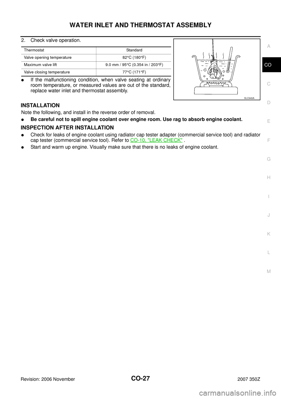
2. Check valve operation.
�If the malfunctioning condition, when valve seating at ordinary
room temperature, or measured values are out of the standard,
replace water inlet and thermostat assembly.
INSTALLATION
Note the following, and install in the reverse order of removal.
�Be careful not to spill engine coolant over engine room. Use rag to absorb engine coolant.
INSPECTION AFTER INSTALLATION
�Check for leaks of engine coolant using radiator cap tester adapter (commercial service tool) and radiator
cap tester (commercial service tool). Refer to CO-10, "
LEAK CHECK" .
�Start and warm up engine. Visually make sure that there is no leaks of engine coolant.
Thermostat Standard
Valve opening temperature 82°C (180°F)
Maximum valve lift 9.0 mm / 95°C (0.354 in / 203°F)
Valve closing temperature 77°C (171°F)
SLC949A
Page 29 of 30
WATER OUTLET AND WATER PIPING
CO-29
C
D
E
F
G
H
I
J
K
L
MA
CO
Revision: 2006 November2007 350Z
CAUTION:
Be careful not to damage engine coolant temperature sensor.
8. Remove oil level gauge and guide. Refer to EM-44, "
FRONT TIMING CHAIN CASE" .
9. Remove water outlet, heater pipe, water bypass hoses and water pipe.
INSTALLATION
Note the following, and install in the reverse order of removal.
�Securely insert each hose, and install clamp at a position where it does not interfere with the pipe bulge.
�When inserting water pipe into water outlet, apply neutral detergent to O-ring.
INSPECTION AFTER INSTALLATION
�Check for leaks of engine coolant using radiator cap tester adapter (commercial service tool) and radiator
cap tester (commercial service tool). Refer to CO-10, "
LEAK CHECK" .
�Start and warm up engine. Visually make sure that there is no leaks of engine coolant.