CO-26
WATER INLET AND THERMOSTAT ASSEMBLY
Revision: 2006 November2007 350Z
WATER INLET AND THERMOSTAT ASSEMBLYPFP:21200
Removal and InstallationNBS00023
�Refer to GI-11, "Components" for symbol marks in the figure.
REMOVAL
1. Remove undercover with power tool.
2. Drain engine coolant from radiator drain plug at the bottom of radiator. Refer to CO-10, "
Changing Engine
Coolant" .
CAUTION:
�Perform this step when engine is cold.
�Do not spill engine coolant on drive belts.
3. Remove air duct and air cleaner case (LH). Refer to EM-15, "
AIR CLEANER AND AIR DUCT" .
4. Disconnect radiator hose (lower) from water inlet and thermostat assembly.
5. Remove intake valve timing control solenoid.
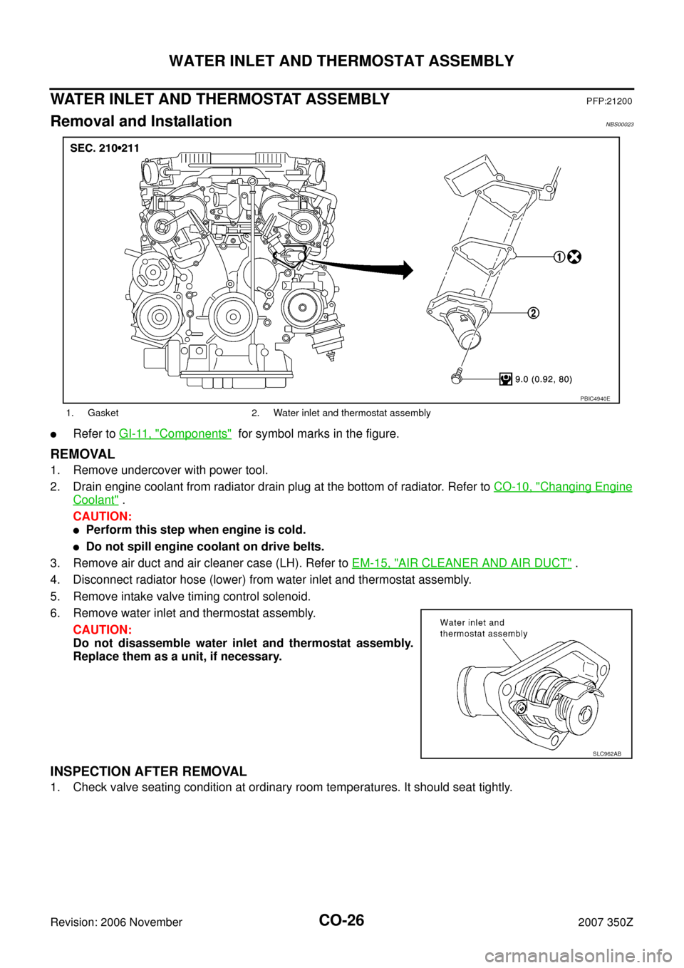
6. Remove water inlet and thermostat assembly.
CAUTION:
Do not disassemble water inlet and thermostat assembly.
Replace them as a unit, if necessary.
INSPECTION AFTER REMOVAL
1. Check valve seating condition at ordinary room temperatures. It should seat tightly.
1. Gasket 2. Water inlet and thermostat assembly
PBIC4940E
SLC962AB
CO-28
WATER OUTLET AND WATER PIPING
Revision: 2006 November2007 350Z
WATER OUTLET AND WATER PIPINGPFP:11060
Removal and InstallationNBS00024
�Refer to GI-11, "Components" for symbol marks in the figure.
REMOVAL
1. Remove undercover with power tool.
2. Drain engine coolant from radiator drain plug at the bottom of radiator, and from water drain plug at the
front of cylinder block. Refer to CO-10, "
Changing Engine Coolant" and CO-23, "WATER PUMP" .
CAUTION:
�Perform this step when engine is cold.
�Do not spill engine coolant on drive belts.
3. Remove engine cover with power tool. Refer to EM-17, "
INTAKE MANIFOLD COLLECTOR" .
4. Remove air duct and air cleaner case (RH, LH). Refer to EM-15, "
AIR CLEANER AND AIR DUCT" .
5. Remove radiator hose (upper), heater hoses and water hoses.
6. Remove the following parts, when remove water outlet.
�A/T fluid charging pipe (A/T models): Refer to AT- 2 4 2 , "TRANSMISSION ASSEMBLY" .
�Intake manifold collector: Refer to EM-17, "INTAKE MANIFOLD COLLECTOR" .
7. Remove engine coolant temperature sensor as necessary.
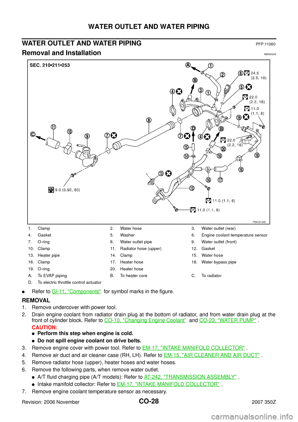
1. Clamp 2. Water hose 3. Water outlet (rear)
4. Gasket 5. Washer 6. Engine coolant temperature sensor
7. O-ring 8. Water outlet pipe 9. Water outlet (front)
10. Clamp 11. Radiator hose (upper) 12. Gasket
13. Heater pipe 14. Clamp 15. Water hose
16. Clamp 17. Heater hose 18. Water bypass pipe
19. O-ring 20. Heater hose
A. To EVAP piping B. To heater core C. To radiator
D. To electric throttle control actuator
PBIC5134E