CO-2
PRECAUTIONS
Revision: 2006 November2007 350Z
PRECAUTIONSPFP:00001
Precautions for Supplemental Restraint System (SRS) “AIR BAG” and “SEAT
BELT PRE-TENSIONER”
NBS0001M
The Supplemental Restraint System such as “AIR BAG” and “SEAT BELT PRE-TENSIONER”, used along
with a front seat belt, helps to reduce the risk or severity of injury to the driver and front passenger for certain
types of collision. This system includes seat belt switch inputs and dual stage front air bag modules. The SRS
system uses the seat belt switches to determine the front air bag deployment, and may only deploy one front
air bag, depending on the severity of a collision and whether the front occupants are belted or unbelted.
Information necessary to service the system safely is included in the SRS and SB section of this Service Man-
ual.
WARNING:
�To avoid rendering the SRS inoperative, which could increase the risk of personal injury or death
in the event of a collision which would result in air bag inflation, all maintenance must be per-
formed by an authorized NISSAN/INFINITI dealer.
�Improper maintenance, including incorrect removal and installation of the SRS, can lead to per-
sonal injury caused by unintentional activation of the system. For removal of Spiral Cable and Air
Bag Module, see the SRS section.
�Do not use electrical test equipment on any circuit related to the SRS unless instructed to in this
Service Manual. SRS wiring harnesses can be identified by yellow and/or orange harnesses or
harness connectors.
Precautions for Battery ServiceNBS0001N
Before disconnecting the battery, lower both the driver and passenger windows. This will prevent any interfer-
ence between the window edge and the vehicle when the door is opened/closed. During normal operation, the
window slightly raises and lowers automatically to prevent any window to vehicle interference. The automatic
window function will not work with the battery disconnected.
Precautions for Liquid GasketNBS0001O
REMOVAL OF LIQUID GASKET SEALING
�After removing mounting bolts and nuts, separate the mating
surface using seal cutter (SST) and remove old liquid gasket
sealing.
CAUTION:
Be careful not to damage the mating surfaces.
�Tap seal cutter to insert it, and then slide it by tapping on the
side as shown in the figure.
�In areas where seal cutter (SST) is difficult to use, use plastic
hammer to lightly tap the parts, to remove it.
CAUTION:
If for some unavoidable reason tool such as screwdriver is
used, be careful not to damage the mating surfaces.
LIQUID GASKET APPLICATION PROCEDURE
1. Using scraper, remove old liquid gasket adhering to the liquid
gasket application surface and the mating surface.
�Remove liquid gasket completely from the groove of the liquid
gasket application surface, mounting bolts, and bolt holes.
2. Wipe the liquid gasket application surface and the mating sur-
face with white gasoline (lighting and heating use) to remove
adhering moisture, grease and foreign materials.
PBIC0002E
PBIC0003E
WATER PUMP
CO-23
C
D
E
F
G
H
I
J
K
L
MA
CO
Revision: 2006 November2007 350Z
WAT E R P U MPPFP:21020
Removal and InstallationNBS00022
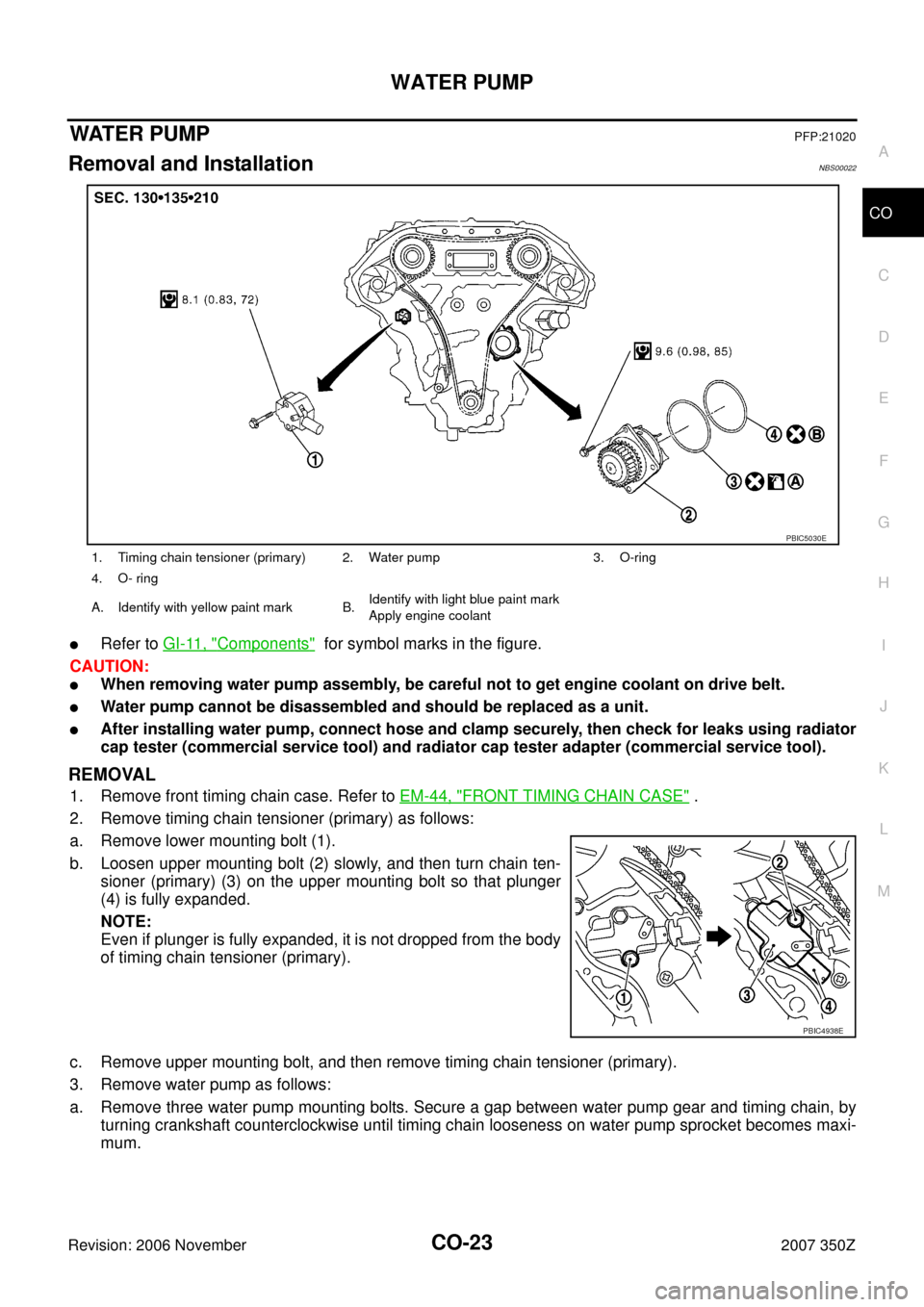
�Refer to GI-11, "Components" for symbol marks in the figure.
CAUTION:
�When removing water pump assembly, be careful not to get engine coolant on drive belt.
�Water pump cannot be disassembled and should be replaced as a unit.
�After installing water pump, connect hose and clamp securely, then check for leaks using radiator
cap tester (commercial service tool) and radiator cap tester adapter (commercial service tool).
REMOVAL
1. Remove front timing chain case. Refer to EM-44, "FRONT TIMING CHAIN CASE" .
2. Remove timing chain tensioner (primary) as follows:
a. Remove lower mounting bolt (1).
b. Loosen upper mounting bolt (2) slowly, and then turn chain ten-
sioner (primary) (3) on the upper mounting bolt so that plunger
(4) is fully expanded.
NOTE:
Even if plunger is fully expanded, it is not dropped from the body
of timing chain tensioner (primary).
c. Remove upper mounting bolt, and then remove timing chain tensioner (primary).
3. Remove water pump as follows:
a. Remove three water pump mounting bolts. Secure a gap between water pump gear and timing chain, by
turning crankshaft counterclockwise until timing chain looseness on water pump sprocket becomes maxi-
mum.
1. Timing chain tensioner (primary) 2. Water pump 3. O-ring
4. O- ring
A. Identify with yellow paint mark B.Identify with light blue paint mark
Apply engine coolant
PBIC5030E
PBIC4938E
CO-24
WATER PUMP
Revision: 2006 November2007 350Z
b. Screw M8 bolts (A) [pitch: 1.25 mm (0.049 in) length: approx. 50
mm (1.97 in)] into water pumps upper and lower mounting bolt
holes until they reach timing chain case. Then, alternately
tighten each bolt for a half turn, and pull out water pump (1).
CAUTION:
�Pull straight out while preventing vane from contacting
socket in installation area.
�Remove water pump without causing sprocket to contact
timing chain.
c. Remove M8 bolts and O-rings from water pump (1).
CAUTION:
Do not disassemble water pump.
INSPECTION AFTER REMOVAL
�Check for badly rusted or corroded water pump body assembly.
�Check for rough operation due to excessive end play.
�Replace water pump, if necessary.
INSTALLATION
1. Install new O-rings to water pump.
�Apply engine oil to O-rings (1) and engine coolant to O-ring
(3) as shown in the figure.
�Locate O-ring (1) with yellow paint mark (A) to engine front
side.
�Locate O-ring (3) with light blue paint mark (B) to rear side.
2. Install water pump.
CAUTION:
Do not allow cylinder block to nip O-rings when installing water pump.
�Make sure that timing chain and water pump sprocket are engaged.
�Insert water pump by tightening mounting bolts alternately and evenly.
3. Install timing chain tensioner (primary) as follows:
a. Turn crankshaft clockwise so that timing chain on the timing chain tensioner (primary) side is loose.
PBIC4939E
SLC943A
2 : Water pump
PBIC5074E
 “AIR BAG” and “SEAT
BELT PRE-TENSIONER”
NBS0001M
The Supplemental Re")
![NISSAN 350Z 2007 Z33 Engine Cooling System Workshop Manual CO-24
WATER PUMP
Revision: 2006 November2007 350Z
b. Screw M8 bolts (A) [pitch: 1.25 mm (0.049 in) length: approx. 50
mm (1.97 in)] into water pumps upper and lower mounting bolt
holes until they reac](/manual-img/5/763/w960_763-23.png "NISSAN 350Z 2007 Z33 Engine Cooling System Workshop Manual CO-24
WATER PUMP
Revision: 2006 November2007 350Z
b. Screw M8 bolts (A) [pitch: 1.25 mm (0.049 in) length: approx. 50
mm (1.97 in)] into water pumps upper and lower mounting bolt
holes until they reac")