Page 588 of 720
EC-588
DTC P1239, P2135 TP SENSOR
Revision: 2006 November2007 350Z
Diagnostic ProcedureNBS000HA
1. CHECK GROUND CONNECTIONS
Models with VDC system, navigation system or telephone
1. Turn ignition switch OFF.
2. Loosen and retighten ground screws on the body. Refer to EC-150, "
Ground Inspection" .
Models without VDC system, navigation system and telephone
1. Turn ignition switch OFF.
2. Loosen and retighten ground screws on the body. Refer to EC-150, "
Ground Inspection" .
OK or NG
OK >> GO TO 2.
NG >> Repair or replace ground connections.
1. Body ground E17 2. Body ground E43 3. Body ground B102
:Vehicle front
1. Body ground E17 2. Body ground E43 3. Body ground F152
(Passenger side view with dash side
finisher removed)
:Vehicle front
PBIB3560E
PBIB3561E
Page 606 of 720
EC-606
DTC P1564 ASCD STEERING SWITCH
Revision: 2006 November2007 350Z
Diagnostic ProcedureNBS000FY
1. CHECK GROUND CONNECTIONS
Models with VDC system, navigation system or telephone
1. Turn ignition switch OFF.
2. Loosen and retighten ground screws on the body. Refer to EC-150, "
Ground Inspection" .
Models without VDC system, navigation system and telephone
1. Turn ignition switch OFF.
2. Loosen and retighten ground screws on the body. Refer to EC-150, "
Ground Inspection" .
OK or NG
OK >> GO TO 2.
NG >> Repair or replace ground connections.
1. Body ground E17 2. Body ground E43 3. Body ground B102
:Vehicle front
1. Body ground E17 2. Body ground E43 3. Body ground F152
(Passenger side view with dash side
finisher removed)
:Vehicle front
PBIB3560E
PBIB3561E
Page 625 of 720

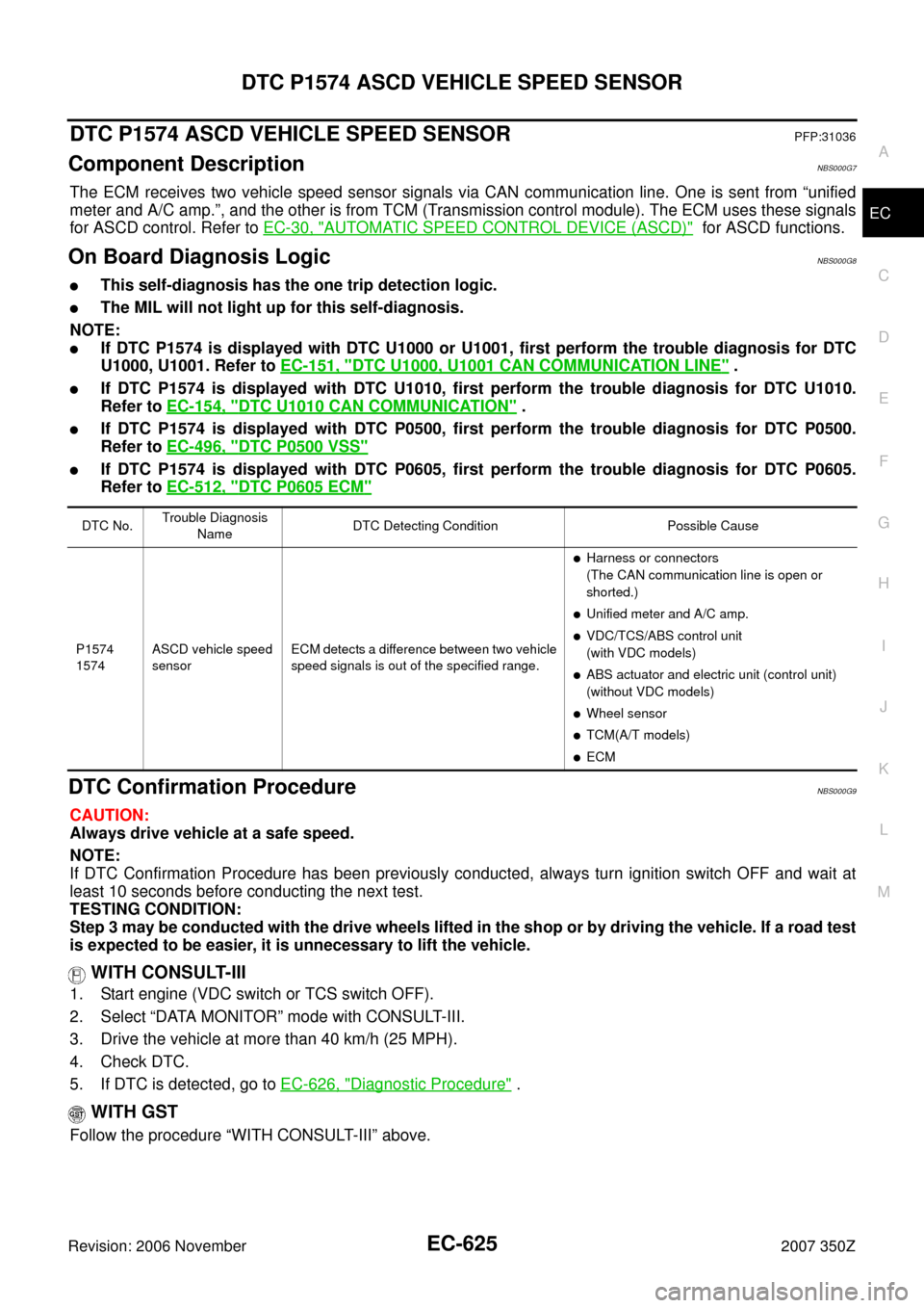
DTC P1574 ASCD VEHICLE SPEED SENSOR
EC-625
C
D
E
F
G
H
I
J
K
L
MA
EC
Revision: 2006 November2007 350Z
DTC P1574 ASCD VEHICLE SPEED SENSORPFP:31036
Component DescriptionNBS000G7
The ECM receives two vehicle speed sensor signals via CAN communication line. One is sent from “unified
meter and A/C amp.”, and the other is from TCM (Transmission control module). The ECM uses these signals
for ASCD control. Refer to EC-30, "
AUTOMATIC SPEED CONTROL DEVICE (ASCD)" for ASCD functions.
On Board Diagnosis LogicNBS000G8
�This self-diagnosis has the one trip detection logic.
�The MIL will not light up for this self-diagnosis.
NOTE:
�If DTC P1574 is displayed with DTC U1000 or U1001, first perform the trouble diagnosis for DTC
U1000, U1001. Refer to EC-151, "
DTC U1000, U1001 CAN COMMUNICATION LINE" .
�If DTC P1574 is displayed with DTC U1010, first perform the trouble diagnosis for DTC U1010.
Refer to EC-154, "
DTC U1010 CAN COMMUNICATION" .
�If DTC P1574 is displayed with DTC P0500, first perform the trouble diagnosis for DTC P0500.
Refer to EC-496, "
DTC P0500 VSS"
�If DTC P1574 is displayed with DTC P0605, first perform the trouble diagnosis for DTC P0605.
Refer to EC-512, "
DTC P0605 ECM"
DTC Confirmation ProcedureNBS000G9
CAUTION:
Always drive vehicle at a safe speed.
NOTE:
If DTC Confirmation Procedure has been previously conducted, always turn ignition switch OFF and wait at
least 10 seconds before conducting the next test.
TESTING CONDITION:
Step 3 may be conducted with the drive wheels lifted in the shop or by driving the vehicle. If a road test
is expected to be easier, it is unnecessary to lift the vehicle.
WITH CONSULT-III
1. Start engine (VDC switch or TCS switch OFF).
2. Select “DATA MONITOR” mode with CONSULT-III.
3. Drive the vehicle at more than 40 km/h (25 MPH).
4. Check DTC.
5. If DTC is detected, go to EC-626, "
Diagnostic Procedure" .
WITH GST
Follow the procedure “WITH CONSULT-III” above.
DTC No.Trouble Diagnosis
NameDTC Detecting Condition Possible Cause
P1574
1574ASCD vehicle speed
sensorECM detects a difference between two vehicle
speed signals is out of the specified range.
�Harness or connectors
(The CAN communication line is open or
shorted.)
�Unified meter and A/C amp.
�VDC/TCS/ABS control unit
(with VDC models)
�ABS actuator and electric unit (control unit)
(without VDC models)
�Wheel sensor
�TCM(A/T models)
�ECM
Page 627 of 720

DTC P1715 INPUT SPEED SENSOR (TURBINE REVOLUTION SENSOR)
EC-627
C
D
E
F
G
H
I
J
K
L
MA
EC
Revision: 2006 November2007 350Z
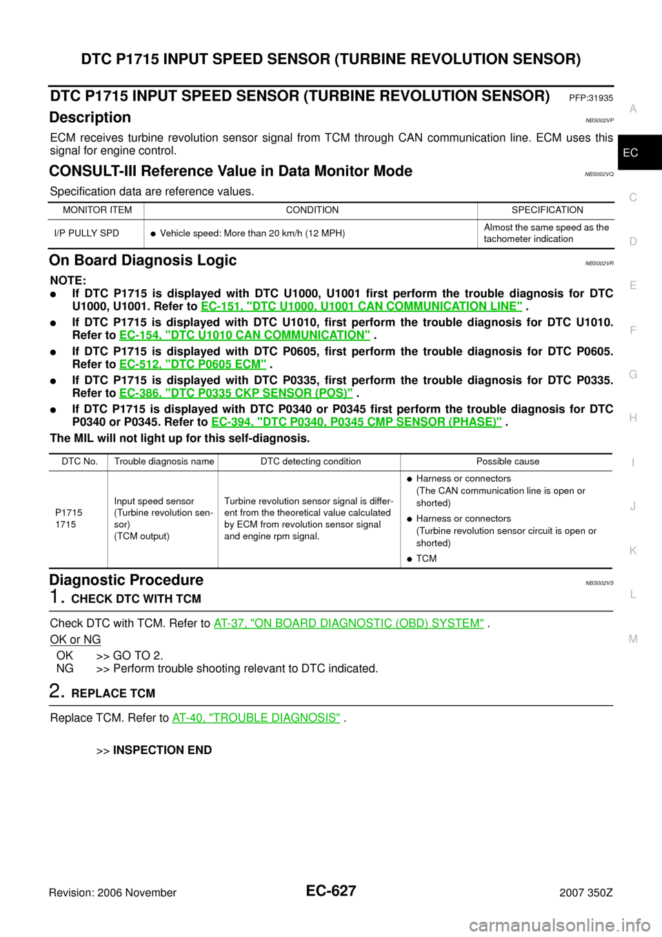
DTC P1715 INPUT SPEED SENSOR (TURBINE REVOLUTION SENSOR)PFP:31935
DescriptionNBS002VP
ECM receives turbine revolution sensor signal from TCM through CAN communication line. ECM uses this
signal for engine control.
CONSULT-III Reference Value in Data Monitor ModeNBS002VQ
Specification data are reference values.
On Board Diagnosis LogicNBS002VR
NOTE:
�If DTC P1715 is displayed with DTC U1000, U1001 first perform the trouble diagnosis for DTC
U1000, U1001. Refer to EC-151, "
DTC U1000, U1001 CAN COMMUNICATION LINE" .
�If DTC P1715 is displayed with DTC U1010, first perform the trouble diagnosis for DTC U1010.
Refer to EC-154, "
DTC U1010 CAN COMMUNICATION" .
�If DTC P1715 is displayed with DTC P0605, first perform the trouble diagnosis for DTC P0605.
Refer to EC-512, "
DTC P0605 ECM" .
�If DTC P1715 is displayed with DTC P0335, first perform the trouble diagnosis for DTC P0335.
Refer to EC-386, "
DTC P0335 CKP SENSOR (POS)" .
�If DTC P1715 is displayed with DTC P0340 or P0345 first perform the trouble diagnosis for DTC
P0340 or P0345. Refer to EC-394, "
DTC P0340, P0345 CMP SENSOR (PHASE)" .
The MIL will not light up for this self-diagnosis.
Diagnostic ProcedureNBS002VS
1. CHECK DTC WITH TCM
Check DTC with TCM. Refer to AT- 3 7 , "
ON BOARD DIAGNOSTIC (OBD) SYSTEM" .
OK or NG
OK >> GO TO 2.
NG >> Perform trouble shooting relevant to DTC indicated.
2. REPLACE TCM
Replace TCM. Refer to AT- 4 0 , "
TROUBLE DIAGNOSIS" .
>>INSPECTION END
MONITOR ITEM CONDITION SPECIFICATION
I/P PULLY SPD
�Vehicle speed: More than 20 km/h (12 MPH)Almost the same speed as the
tachometer indication
DTC No. Trouble diagnosis name DTC detecting condition Possible cause
P1715
1715Input speed sensor
(Turbine revolution sen-
sor)
(TCM output)Turbine revolution sensor signal is differ-
ent from the theoretical value calculated
by ECM from revolution sensor signal
and engine rpm signal.
�Harness or connectors
(The CAN communication line is open or
shorted)
�Harness or connectors
(Turbine revolution sensor circuit is open or
shorted)
�TCM
Page 637 of 720
DTC P2122, P2123 APP SENSOR
EC-637
C
D
E
F
G
H
I
J
K
L
MA
EC
Revision: 2006 November2007 350Z
Diagnostic ProcedureNBS000GU
1. CHECK GROUND CONNECTIONS
Models with VDC system, navigation system or telephone
1. Turn ignition switch OFF.
2. Loosen and retighten ground screws on the body. Refer to EC-150, "
Ground Inspection" .
Models without VDC system, navigation system and telephone
1. Turn ignition switch OFF.
2. Loosen and retighten ground screws on the body. Refer to EC-150, "
Ground Inspection" .
OK or NG
OK >> GO TO 2.
NG >> Repair or replace ground connections.
1. Body ground E17 2. Body ground E43 3. Body ground B102
:Vehicle front
1. Body ground E17 2. Body ground E43 3. Body ground F152
(Passenger side view with dash side
finisher removed)
:Vehicle front
PBIB3560E
PBIB3561E
Page 645 of 720
DTC P2127, P2128 APP SENSOR
EC-645
C
D
E
F
G
H
I
J
K
L
MA
EC
Revision: 2006 November2007 350Z
Diagnostic ProcedureNBS000H2
1. CHECK GROUND CONNECTIONS
Models with VDC system, navigation system or telephone
1. Turn ignition switch OFF.
2. Loosen and retighten ground screws on the body. Refer to EC-150, "
Ground Inspection" .
Models without VDC system, navigation system and telephone
1. Turn ignition switch OFF.
2. Loosen and retighten ground screws on the body. Refer to EC-150, "
Ground Inspection" .
OK or NG
OK >> GO TO 2.
NG >> Repair or replace ground connections.
1. Body ground E17 2. Body ground E43 3. Body ground B102
:Vehicle front
1. Body ground E17 2. Body ground E43 3. Body ground F152
(Passenger side view with dash side
finisher removed)
:Vehicle front
PBIB3560E
PBIB3561E
Page 654 of 720
EC-654
DTC P2138 APP SENSOR
Revision: 2006 November2007 350Z
Diagnostic ProcedureNBS000HI
1. CHECK GROUND CONNECTIONS
Models with VDC system, navigation system or telephone
1. Turn ignition switch OFF.
2. Loosen and retighten ground screws on the body. Refer to EC-150, "
Ground Inspection" .
Models without VDC system, navigation system and telephone
1. Turn ignition switch OFF.
2. Loosen and retighten ground screws on the body. Refer to EC-150, "
Ground Inspection" .
OK or NG
OK >> GO TO 2.
NG >> Repair or replace ground connections.
1. Body ground E17 2. Body ground E43 3. Body ground B102
:Vehicle front
1. Body ground E17 2. Body ground E43 3. Body ground F152
(Passenger side view with dash side
finisher removed)
:Vehicle front
PBIB3560E
PBIB3561E
Page 665 of 720
DTC P2A00, P2A03 A/F SENSOR 1
EC-665
C
D
E
F
G
H
I
J
K
L
MA
EC
Revision: 2006 November2007 350Z
Diagnostic ProcedureNBS001NX
1. CHECK GROUND CONNECTIONS
Models with VDC system, navigation system or telephone
1. Turn ignition switch OFF.
2. Loosen and retighten ground screws on the body. Refer to EC-150, "
Ground Inspection" .
Models without VDC system, navigation system and telephone
1. Turn ignition switch OFF.
2. Loosen and retighten ground screws on the body. Refer to EC-150, "
Ground Inspection" .
OK or NG
OK >> GO TO 2.
NG >> Repair or replace ground connections.
1. Body ground E17 2. Body ground E43 3. Body ground B102
:Vehicle front
1. Body ground E17 2. Body ground E43 3. Body ground F152
(Passenger side view with dash side
finisher removed)
:Vehicle front
PBIB3560E
PBIB3561E