Page 496 of 720

EC-496
DTC P0500 VSS
Revision: 2006 November2007 350Z
DTC P0500 VSSPFP:32702
DescriptionNBS000AH
NOTE:
�If DTC P0500 is displayed with DTC U1000 or U1001, first perform the trouble diagnosis for DTC
U1000, U1001. Refer to EC-151, "
DTC U1000, U1001 CAN COMMUNICATION LINE" .
�If DTC P0500 is displayed with DTC U1010, first perform the trouble diagnosis for DTC U1010.
Refer to EC-154, "
DTC U1010 CAN COMMUNICATION" .
The vehicle speed signal is sent to the “unified meter and A/C amp”. from the VDC/TCS/ABS control unit (with
VDC models) or “ABS actuator and electric unit (control unit)” (without VDC models) by CAN communication
line. The unified meter and A/C amp. then sends the signal to the ECM by CAN communication line.
On Board Diagnosis LogicNBS000AI
FAIL-SAFE MODE
When the malfunction is detected, the ECM enters fail-safe mode.
DTC Confirmation ProcedureNBS000AJ
CAUTION:
Always drive vehicle at a safe speed.
NOTE:
If DTC Confirmation Procedure has been previously conducted, always turn ignition switch OFF and wait at
least 10 seconds before conducting the next test.
TESTING CONDITION:
Steps 1 and 2 may be conducted with the drive wheels lifted in the shop or by driving the vehicle. If a
road test is expected to be easier, it is unnecessary to lift the vehicle.
WITH CONSULT-III
1. Start engine (VDC switch or TCS switch OFF).
2. Read “VHCL SPEED SE” in “DATA MONITOR” mode with CONSULT-III. The vehicle speed on CON-
SULT-III should exceed 10 km/h (6 MPH) when rotating wheels with suitable gear position.
If NG, go to EC-497, "
Diagnostic Procedure" .
If OK, go to following step.
3. Select “DATA MONITOR” mode with CONSULT-III.
4. Warm engine up to normal operating temperature.
5. Maintain the following conditions for at least 60 consecutive seconds.
DTC No. Trouble diagnosis name DTC detecting condition Possible cause
P0500
0500Vehicle speed sensorThe almost 0 km/h (0 MPH) signal from
vehicle speed sensor is sent to ECM
even when vehicle is being driven.
�Harness or connectors
(The CAN communication line is open or
shorted)
�Harness or connectors
(The vehicle speed signal circuit is open or
shorted)
�Wheel sensor
�Unified meter and A/C amp.
�VDC/TCS/ABS control unit (with VDC models)
�ABS actuator and electric unit (control unit)
(without VDC models)
Detected items Engine operating condition in fail-safe mode
Vehicle speed sensorWhen the fail-safe system for vehicle speed sensor is activated, the cooling fan operates (High) while
engine is running.
ENG SPEED1,800 - 6,000 rpm (A/T)
1,800 - 6,000 rpm (M/T)
COOLAN TEMP/S More than 70°C (158°F)
Page 505 of 720
DTC P0550 PSP SENSOR
EC-505
C
D
E
F
G
H
I
J
K
L
MA
EC
Revision: 2006 November2007 350Z
Diagnostic ProcedureNBS000AZ
1. CHECK GROUND CONNECTIONS
Models with VDC system, navigation system or telephone
1. Turn ignition switch OFF.
2. Loosen and retighten ground screws on the body. Refer to EC-150, "
Ground Inspection" .
Models without VDC system, navigation system and telephone
1. Turn ignition switch OFF.
2. Loosen and retighten ground screws on the body. Refer to EC-150, "
Ground Inspection" .
OK or NG
OK >> GO TO 2.
NG >> Repair or replace ground connections.
1. Body ground E17 2. Body ground E43 3. Body ground B102
:Vehicle front
1. Body ground E17 2. Body ground E43 3. Body ground F152
(Passenger side view with dash side
finisher removed)
:Vehicle front
PBIB3560E
PBIB3561E
Page 517 of 720
DTC P0643 SENSOR POWER SUPPLY
EC-517
C
D
E
F
G
H
I
J
K
L
MA
EC
Revision: 2006 November2007 350Z
Diagnostic ProcedureNBS000DZ
1. CHECK GROUND CONNECTIONS
Models with VDC system, navigation system or telephone
1. Turn ignition switch OFF.
2. Loosen and retighten ground screws on the body. Refer to EC-150, "
Ground Inspection" .
Models without VDC system, navigation system and telephone
1. Turn ignition switch OFF.
2. Loosen and retighten ground screws on the body. Refer to EC-150, "
Ground Inspection" .
OK or NG
OK >> GO TO 2.
NG >> Repair or replace ground connections.
1. Body ground E17 2. Body ground E43 3. Body ground B102
:Vehicle front
1. Body ground E17 2. Body ground E43 3. Body ground F152
(Passenger side view with dash side
finisher removed)
:Vehicle front
PBIB3560E
PBIB3561E
Page 534 of 720
EC-534
DTC P1078 P1084 EVT CONTROL POSITION SENSOR
Revision: 2006 November2007 350Z
Diagnostic ProcedureNBS000BO
1. CHECK GROUND CONNECTIONS
Models with VDC system, navigation system or telephone
1. Turn ignition switch OFF.
2. Loosen and retighten ground screws on the body. Refer to EC-150, "
Ground Inspection" .
Models without VDC system, navigation system and telephone
1. Turn ignition switch OFF.
2. Loosen and retighten ground screws on the body. Refer to EC-150, "
Ground Inspection" .
OK or NG
OK >> GO TO 2.
NG >> Repair or replace ground connections.
1. Body ground E17 2. Body ground E43 3. Body ground B102
:Vehicle front
1. Body ground E17 2. Body ground E43 3. Body ground F152
(Passenger side view with dash side
finisher removed)
:Vehicle front
PBIB3560E
PBIB3561E
Page 542 of 720

EC-542
DTC P1212 TCS COMMUNICATION LINE
Revision: 2006 November2007 350Z
DTC P1212 TCS COMMUNICATION LINEPFP:47850
DescriptionNBS000DA
NOTE:
�If DTC P1212 is displayed with DTC U1000 or U1001, first perform the trouble diagnosis for DTC
U1000, U1001. Refer to EC-151, "
DTC U1000, U1001 CAN COMMUNICATION LINE" .
�If DTC P1212 is displayed with DTC U1010, first perform the trouble diagnosis for DTC U1010.
Refer to EC-154, "
DTC U1010 CAN COMMUNICATION" .
This CAN communication line is used to control the smooth engine operation during the TCS operation. Pulse
signals are exchanged between ECM and VDC/TCS/ABS control unit (with VDC models) or “ABS actuator
and electric unit (control unit)” (without VDC models).
Be sure to erase the malfunction information such as DTC not only for VDC/TCS/ABS control unit
(with VDC models) or “ABS actuator and electric unit (control unit)” (without VDC models) but also for
ECM after TCS related repair.
On Board Diagnosis LogicNBS000DB
�Freeze frame data is not stored in the ECM for this self-diagnosis.
�The MIL will not light up for this self-diagnosis.
DTC Confirmation ProcedureNBS000DC
TESTING CONDITION:
Before performing the following procedure, confirm that battery voltage is more than 10.5V at idle.
WITH CONSULT-III
1. Start engine and let it idle for at least 10 seconds.
2. Check 1st trip DTC.
3. If 1st trip DTC is detected, go to EC-542, "
Diagnostic Procedure" .
WITH GST
Follow the procedure “WITH CONSULT-III” above.
Diagnostic ProcedureNBS000DD
Go to BRC-82, "TROUBLE DIAGNOSIS" (With VDC models) or BRC-42, "TROUBLE DIAGNOSIS" (Without
VDC models).
DTC No. Trouble diagnosis name DTC detecting condition Possible cause
P1212
1212TCS communication
lineECM can not receive the information
from VDC/TCS/ABS control unit (with
VDC models) or “ABS actuator and elec-
tric unit (control unit)” (without VDC mod-
els) continuously.
�Harness or connectors
(The CAN communication line is open or
shorted.)
�VDC/TCS/ABS control unit (with VDC models)
�ABS actuator and electric unit (control unit)
(without VDC models)
�Dead (Weak) battery
Page 543 of 720

DTC P1217 ENGINE OVER TEMPERATURE
EC-543
C
D
E
F
G
H
I
J
K
L
MA
EC
Revision: 2006 November2007 350Z
DTC P1217 ENGINE OVER TEMPERATUREPFP:00000
DescriptionNBS000DE
SYSTEM DESCRIPTION
NOTE:
�If DTC P1217 is displayed with DTC U1000 or U1001, first perform the trouble diagnosis for DTC
U1000, U1001. Refer to EC-151, "
DTC U1000, U1001 CAN COMMUNICATION LINE" .
�If DTC P1217 is displayed with DTC U1010, first perform the trouble diagnosis for DTC U1010.
Refer to EC-154, "
DTC U1010 CAN COMMUNICATION" .
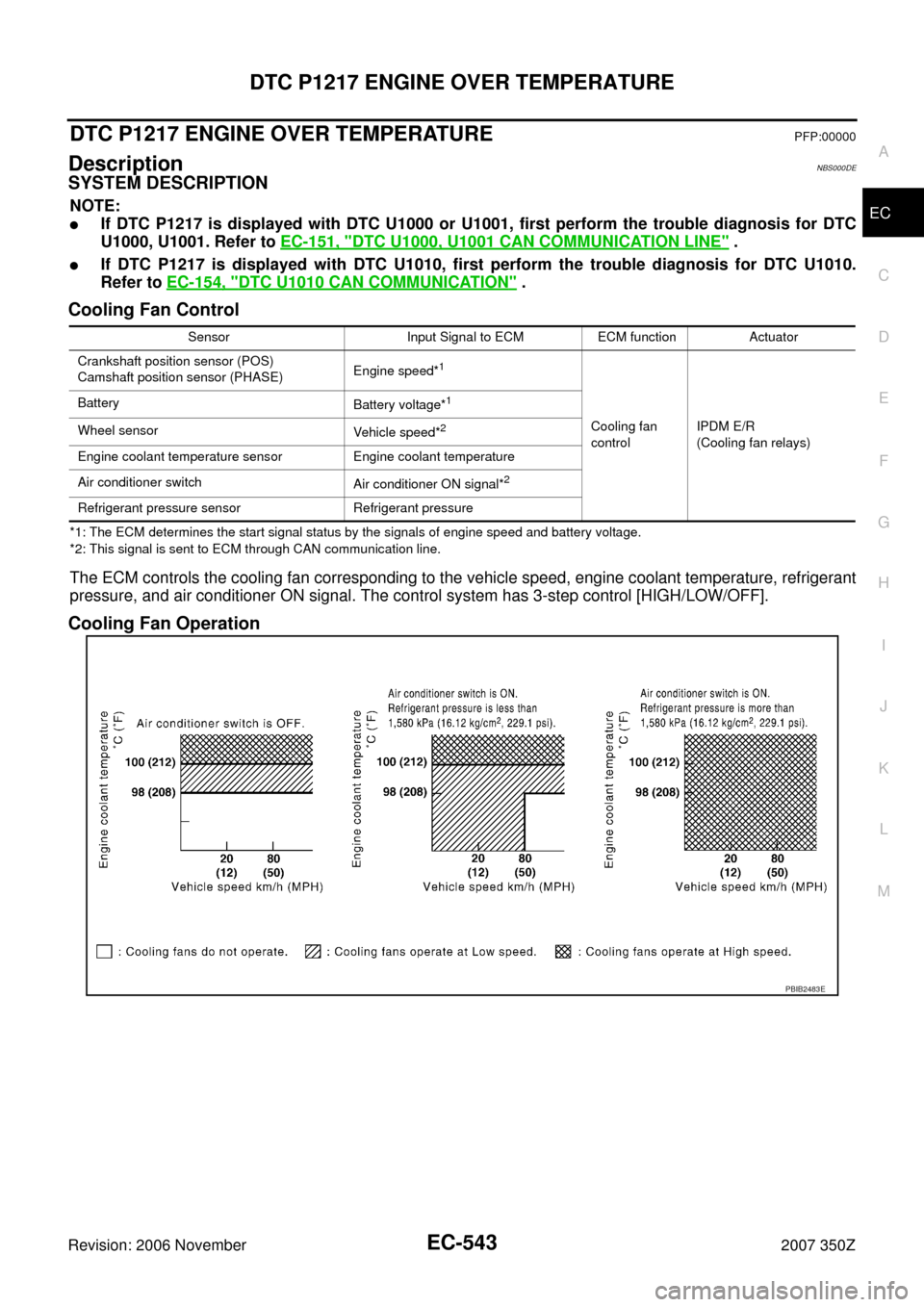
Cooling Fan Control
*1: The ECM determines the start signal status by the signals of engine speed and battery voltage.
*2: This signal is sent to ECM through CAN communication line.
The ECM controls the cooling fan corresponding to the vehicle speed, engine coolant temperature, refrigerant
pressure, and air conditioner ON signal. The control system has 3-step control [HIGH/LOW/OFF].
Cooling Fan Operation
Sensor Input Signal to ECM ECM function Actuator
Crankshaft position sensor (POS)
Camshaft position sensor (PHASE)Engine speed*
1
Cooling fan
controlIPDM E/R
(Cooling fan relays) Battery
Battery voltage*
1
Wheel sensor
Vehicle speed*2
Engine coolant temperature sensor Engine coolant temperature
Air conditioner switch
Air conditioner ON signal*
2
Refrigerant pressure sensor Refrigerant pressure
PBIB2483E
Page 566 of 720

EC-566
DTC P1233, P2101 ELECTRIC THROTTLE CONTROL FUNCTION
Revision: 2006 November2007 350Z
Diagnostic ProcedureNBS000C7
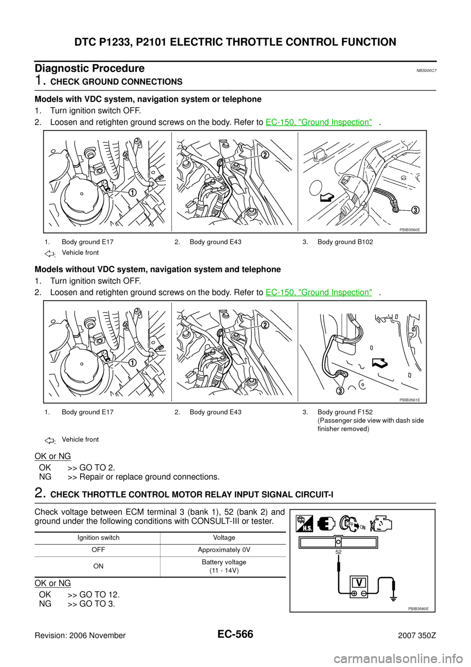
1. CHECK GROUND CONNECTIONS
Models with VDC system, navigation system or telephone
1. Turn ignition switch OFF.
2. Loosen and retighten ground screws on the body. Refer to EC-150, "
Ground Inspection" .
Models without VDC system, navigation system and telephone
1. Turn ignition switch OFF.
2. Loosen and retighten ground screws on the body. Refer to EC-150, "
Ground Inspection" .
OK or NG
OK >> GO TO 2.
NG >> Repair or replace ground connections.
2. CHECK THROTTLE CONTROL MOTOR RELAY INPUT SIGNAL CIRCUIT-I
Check voltage between ECM terminal 3 (bank 1), 52 (bank 2) and
ground under the following conditions with CONSULT-III or tester.
OK or NG
OK >> GO TO 12.
NG >> GO TO 3.
1. Body ground E17 2. Body ground E43 3. Body ground B102
:Vehicle front
1. Body ground E17 2. Body ground E43 3. Body ground F152
(Passenger side view with dash side
finisher removed)
:Vehicle front
PBIB3560E
PBIB3561E
Ignition switch Voltage
OFF Approximately 0V
ONBattery voltage
(11 - 14V)
PBIB3580E
Page 576 of 720
EC-576
DTC P1236, P2118 THROTTLE CONTROL MOTOR
Revision: 2006 November2007 350Z
Diagnostic ProcedureNBS000CK
1. CHECK GROUND CONNECTIONS
Models with VDC system, navigation system or telephone
1. Turn ignition switch OFF.
2. Loosen and retighten ground screws on the body. Refer to EC-150, "
Ground Inspection" .
Models without VDC system, navigation system and telephone
1. Turn ignition switch OFF.
2. Loosen and retighten ground screws on the body. Refer to EC-150, "
Ground Inspection" .
OK or NG
OK >> GO TO 2.
NG >> Repair or replace ground connections.
1. Body ground E17 2. Body ground E43 3. Body ground B102
:Vehicle front
1. Body ground E17 2. Body ground E43 3. Body ground F152
(Passenger side view with dash side
finisher removed)
:Vehicle front
PBIB3560E
PBIB3561E