Page 591 of 720
DTC P1239, P2135 TP SENSOR
EC-591
C
D
E
F
G
H
I
J
K
L
MA
EC
Revision: 2006 November2007 350Z
6. If NG, replace electric throttle control actuator and go to the next step.
7. Perform EC-77, "
Throttle Valve Closed Position Learning" .
8. Perform EC-77, "
Idle Air Volume Learning" .
Removal and InstallationNBS000HC
ELECTRIC THROTTLE CONTROL ACTUATOR
Refer to EM-17, "INTAKE MANIFOLD COLLECTOR" .
Terminal Accelerator pedal Voltage
30 [TP sensor 1 (bank 1)]
31 [TP sensor 1 (bank 2)]Fully released More than 0.36V
Fully depressed Less than 4.75V
34 [TP sensor 2 (bank 1)]
35 [TP sensor 2 (bank 2)]Fully released Less than 4.75V
Fully depressed More than 0.36V
Page 600 of 720

EC-600
DTC P1421 COLD START CONTROL
Revision: 2006 November2007 350Z
DTC P1421 COLD START CONTROLPFP:23710
DescriptionNBS006TX
ECM controls ignition timing and engine idle speed when engine is started with prewarming up condition.
This control promotes the activation of three way catalyst by heating the catalyst and reduces emissions.
On Board Diagnosis LogicNBS006TY
DTC Confirmation ProcedureNBS006TZ
NOTE:
�If DTC Confirmation Procedure has been previously conducted, always turn ignition switch OFF and wait
at least 10 seconds before conducting the next test.
�If DTC P1421 is displayed with other DTC, first perform the trouble diagnosis for other DTC.
TESTING CONDITION:
Before performing the following procedure, confirm that battery voltage is more than 11V at idle.
WITH CONSULT-III
1. Turn ignition switch OFF and wait at least 10 seconds.
2. Turn ignition switch ON.
3. Select “DATA MONITOR” mode with CONSULT-III.
4. Check that the “COOLAN TEMP/S” indication is between 4°C (39°F) and 36°C (97°F).
If “COOLAN TEMP/S” indication is within the specified value, go to the following step.
If “COOLANT TEMP/S” indication is out of the specified value, cool engine down or warm engine up and
go to step 1.
5. Start engine and let it idle for 5 minutes.
6. Check 1st trip DTC.
7. If 1st trip DTC is detected, go to EC-600, "
Diagnostic Procedure" .
WITH GST
Follow the procedure “WITH CONSULT-III” above.
Diagnostic ProcedureNBS006U0
1. PERFORM IDLE AIR VOLUME LEARNING
Perform EC-77, "
Idle Air Volume Learning" .
Is Idle Air Volume Learning carried out successfully?
Ye s o r N o
Yes >> GO TO 2.
No >> Follow the instruction of Idle Air Volume Learning.
2. CHECK INTAKE SYSTEM
Check for the cause of intake air volume lacking. Refer to the following.
�Crushed intake air passage
�Intake air passage clogging
OK or NG
OK >> GO TO 3.
NG >> Repair or replace malfunctioning part
DTC No. Trouble diagnosis name DTC detecting condition Possible cause
P1421
1421Cold start emission reduction
strategy monitoringECM does not control ignition timing and engine
idle speed properly when engine is started with
prewarming up condition.
�Lack of intake air volume
�Fuel injection system
�ECM
Page 601 of 720

DTC P1421 COLD START CONTROL
EC-601
C
D
E
F
G
H
I
J
K
L
MA
EC
Revision: 2006 November2007 350Z
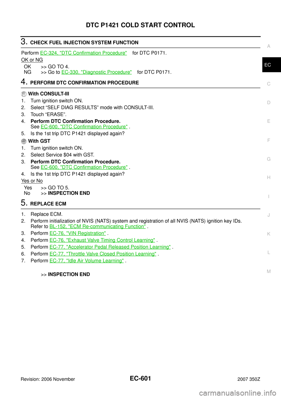
3. CHECK FUEL INJECTION SYSTEM FUNCTION
Perform EC-324, "
DTC Confirmation Procedure" for DTC P0171.
OK or NG
OK >> GO TO 4.
NG >> Go to EC-330, "
Diagnostic Procedure" for DTC P0171.
4. PERFORM DTC CONFIRMATION PROCEDURE
With CONSULT-III
1. Turn ignition switch ON.
2. Select “SELF DIAG RESULTS” mode with CONSULT-III.
3. Touch “ERASE”.
4.Perform DTC Confirmation Procedure.
See EC-600, "
DTC Confirmation Procedure" .
5. Is the 1st trip DTC P1421 displayed again?
With GST
1. Turn ignition switch ON.
2. Select Service $04 with GST.
3.Perform DTC Confirmation Procedure.
See EC-600, "
DTC Confirmation Procedure" .
4. Is the 1st trip DTC P1421 displayed again?
Ye s o r N o
Ye s > > G O T O 5 .
No >>INSPECTION END
5. REPLACE ECM
1. Replace ECM.
2. Perform initialization of NVIS (NATS) system and registration of all NVIS (NATS) ignition key IDs.
Refer to BL-152, "
ECM Re-communicating Function" .
3. Perform EC-76, "
VIN Registration" .
4. Perform EC-76, "
Exhaust Valve Timing Control Learning" .
5. Perform EC-77, "
Accelerator Pedal Released Position Learning" .
6. Perform EC-77, "
Throttle Valve Closed Position Learning" .
7. Perform EC-77, "
Idle Air Volume Learning" .
>>INSPECTION END
Page 639 of 720

DTC P2122, P2123 APP SENSOR
EC-639
C
D
E
F
G
H
I
J
K
L
MA
EC
Revision: 2006 November2007 350Z
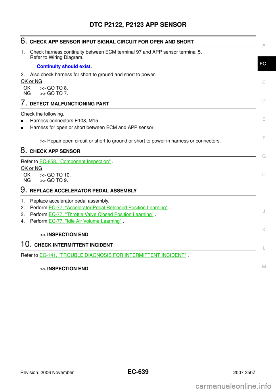
6. CHECK APP SENSOR INPUT SIGNAL CIRCUIT FOR OPEN AND SHORT
1. Check harness continuity between ECM terminal 97 and APP sensor terminal 5.
Refer to Wiring Diagram.
2. Also check harness for short to ground and short to power.
OK or NG
OK >> GO TO 8.
NG >> GO TO 7.
7. DETECT MALFUNCTIONING PART
Check the following.
�Harness connectors E108, M15
�Harness for open or short between ECM and APP sensor
>> Repair open circuit or short to ground or short to power in harness or connectors.
8. CHECK APP SENSOR
Refer to EC-658, "
Component Inspection" .
OK or NG
OK >> GO TO 10.
NG >> GO TO 9.
9. REPLACE ACCELERATOR PEDAL ASSEMBLY
1. Replace accelerator pedal assembly.
2. Perform EC-77, "
Accelerator Pedal Released Position Learning" .
3. Perform EC-77, "
Throttle Valve Closed Position Learning" .
4. Perform EC-77, "
Idle Air Volume Learning" .
>>INSPECTION END
10. CHECK INTERMITTENT INCIDENT
Refer to EC-141, "
TROUBLE DIAGNOSIS FOR INTERMITTENT INCIDENT" .
>>INSPECTION END Continuity should exist.
Page 640 of 720
EC-640
DTC P2122, P2123 APP SENSOR
Revision: 2006 November2007 350Z
Component InspectionNBS000GV
ACCELERATOR PEDAL POSITION SENSOR
1. Reconnect all harness connectors disconnected.
2. Turn ignition switch ON.
3. Check voltage between ECM terminals 97 (APP sensor 1 sig-
nal), 98 (APP sensor 2 signal) and ground under the following
conditions.
4. If NG, replace accelerator pedal assembly and go to next step.
5. Perform EC-77, "
Accelerator Pedal Released Position Learning" .
6. Perform EC-77, "
Throttle Valve Closed Position Learning" .
7. Perform EC-77, "
Idle Air Volume Learning" .
Removal and InstallationNBS000GW
ACCELERATOR PEDAL
Refer to ACC-3, "ACCELERATOR CONTROL SYSTEM" .
Terminal Accelerator pedal Voltage
97
(Accelerator pedal position
sensor 1)Fully released 0.5 - 1.0V
Fully depressed 3.9 - 4.7V
98
(Accelerator pedal position
sensor 2)Fully released 0.15 - 0.60V
Fully depressed 1.95 - 2.40V
PBIB3582E
Page 648 of 720

EC-648
DTC P2127, P2128 APP SENSOR
Revision: 2006 November2007 350Z
9. CHECK APP SENSOR 2 INPUT SIGNAL CIRCUIT FOR OPEN AND SHORT
1. Check harness continuity between ECM terminal 98 and APP sensor terminal 2.
Refer to Wiring Diagram.
2. Also check harness for short to ground and short to power.
OK or NG
OK >> GO TO 11.
NG >> GO TO 10.
10. DETECT MALFUNCTIONING PART
Check the following.
�Harness connectors E108, M15
�Harness for open or short between ECM and APP sensor
>> Repair open circuit or short to ground or short to power in harness or connectors.
11 . CHECK APP SENSOR
Refer to EC-658, "
Component Inspection" .
OK or NG
OK >> GO TO 13.
NG >> GO TO 12.
12. REPLACE ACCELERATOR PEDAL ASSEMBLY
1. Replace accelerator pedal assembly.
2. Perform EC-77, "
Accelerator Pedal Released Position Learning" .
3. Perform EC-77, "
Throttle Valve Closed Position Learning" .
4. Perform EC-77, "
Idle Air Volume Learning" .
>>INSPECTION END
13. CHECK INTERMITTENT INCIDENT
Refer to EC-141, "
TROUBLE DIAGNOSIS FOR INTERMITTENT INCIDENT" .
>>INSPECTION END
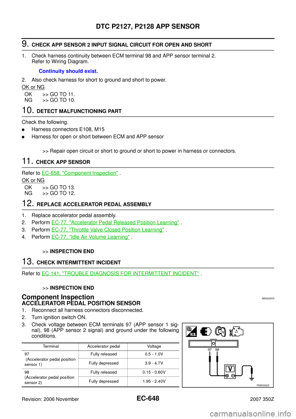
Component InspectionNBS000H3
ACCELERATOR PEDAL POSITION SENSOR
1. Reconnect all harness connectors disconnected.
2. Turn ignition switch ON.
3. Check voltage between ECM terminals 97 (APP sensor 1 sig-
nal), 98 (APP sensor 2 signal) and ground under the following
conditions.Continuity should exist.
Terminal Accelerator pedal Voltage
97
(Accelerator pedal position
sensor 1)Fully released 0.5 - 1.0V
Fully depressed 3.9 - 4.7V
98
(Accelerator pedal position
sensor 2)Fully released 0.15 - 0.60V
Fully depressed 1.95 - 2.40V
PBIB3582E
Page 649 of 720
DTC P2127, P2128 APP SENSOR
EC-649
C
D
E
F
G
H
I
J
K
L
MA
EC
Revision: 2006 November2007 350Z
4. If NG, replace accelerator pedal assembly and go to next step.
5. Perform EC-77, "
Accelerator Pedal Released Position Learning" .
6. Perform EC-77, "
Throttle Valve Closed Position Learning" .
7. Perform EC-77, "
Idle Air Volume Learning" .
Removal and InstallationNBS000H4
ACCELERATOR PEDAL
Refer to ACC-3, "ACCELERATOR CONTROL SYSTEM" .
Page 658 of 720

EC-658
DTC P2138 APP SENSOR
Revision: 2006 November2007 350Z
14. REPLACE ACCELERATOR PEDAL ASSEMBLY
1. Replace accelerator pedal assembly.
2. Perform EC-77, "
Accelerator Pedal Released Position Learning" .
3. Perform EC-77, "
Throttle Valve Closed Position Learning" .
4. Perform EC-77, "
Idle Air Volume Learning" .
>>INSPECTION END
15. CHECK INTERMITTENT INCIDENT
Refer to EC-141, "
TROUBLE DIAGNOSIS FOR INTERMITTENT INCIDENT" .
>>INSPECTION END
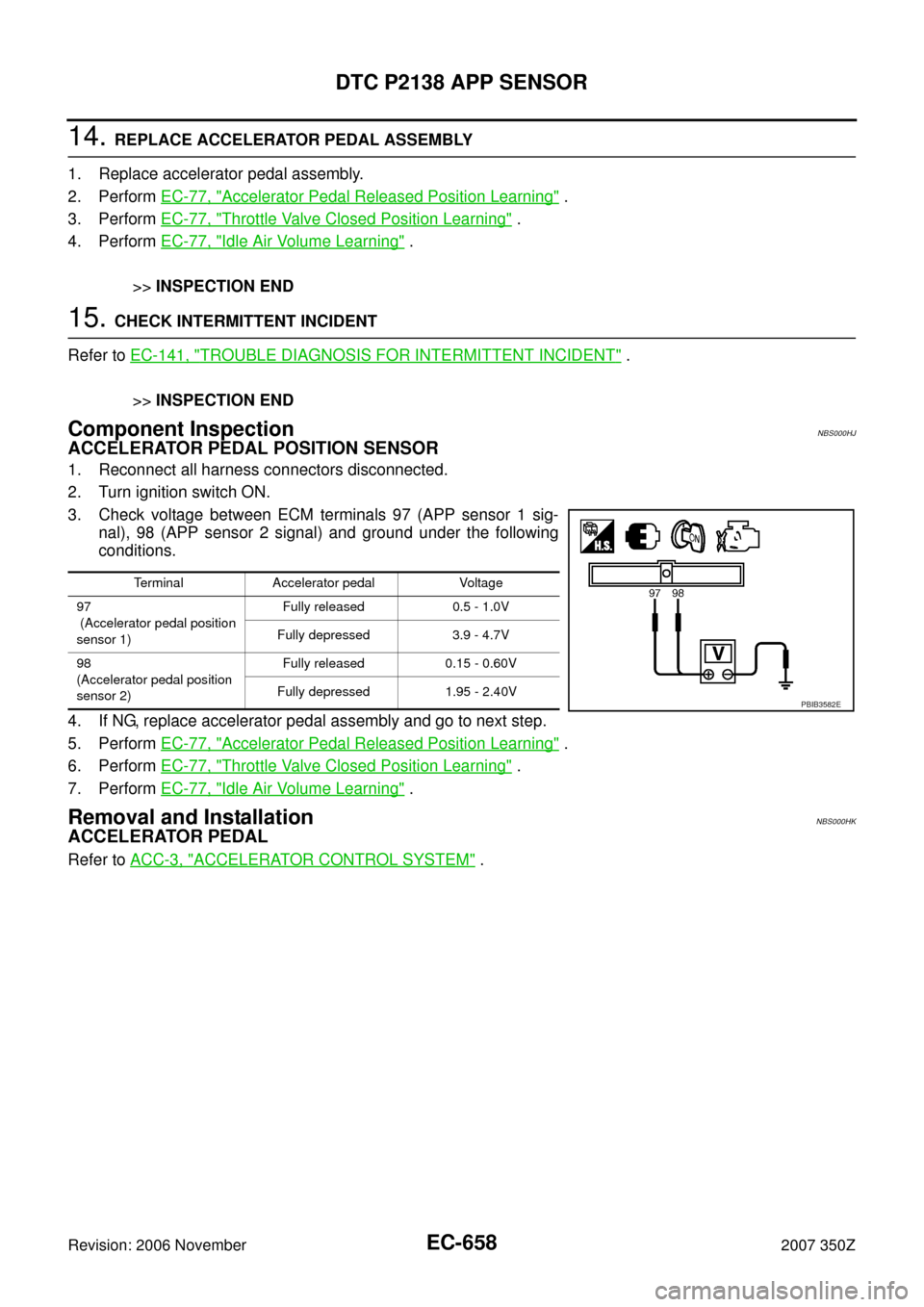
Component InspectionNBS000HJ
ACCELERATOR PEDAL POSITION SENSOR
1. Reconnect all harness connectors disconnected.
2. Turn ignition switch ON.
3. Check voltage between ECM terminals 97 (APP sensor 1 sig-
nal), 98 (APP sensor 2 signal) and ground under the following
conditions.
4. If NG, replace accelerator pedal assembly and go to next step.
5. Perform EC-77, "
Accelerator Pedal Released Position Learning" .
6. Perform EC-77, "
Throttle Valve Closed Position Learning" .
7. Perform EC-77, "
Idle Air Volume Learning" .
Removal and InstallationNBS000HK
ACCELERATOR PEDAL
Refer to ACC-3, "ACCELERATOR CONTROL SYSTEM" .
Terminal Accelerator pedal Voltage
97
(Accelerator pedal position
sensor 1)Fully released 0.5 - 1.0V
Fully depressed 3.9 - 4.7V
98
(Accelerator pedal position
sensor 2)Fully released 0.15 - 0.60V
Fully depressed 1.95 - 2.40V
PBIB3582E