Page 138 of 720

EC-138
TROUBLE DIAGNOSIS - SPECIFICATION VALUE
Revision: 2006 November2007 350Z
17. CHECK “B/FUEL SCHDL”
Select “B/FUEL SCHDL” in “SPEC” of "DATA MONITOR" mode, and make sure that the indication is within the
SP value.
OK or NG
OK >>INSPECTION END
NG (More than the SP value)>>GO TO 18.
NG (Less than the SP value)>>GO TO 25.
18. DETECT MALFUNCTIONING PART
1. Check for the cause of large engine friction. Refer to the following.
–Engine oil level is too high
–Engine oil viscosity
–Belt tension of power steering, alternator, A/C compressor, etc. is excessive
–Noise from engine
–Noise from transmission, etc.
2. Check for the cause of insufficient combustion. Refer to the following.
–Valve clearance malfunction
–Intake valve timing control function malfunction
–Camshaft sprocket installation malfunction, etc.
>> Repair or replace malfunctioning part, and then GO TO 30.
19. CHECK INTAKE SYSTEM
Check for the cause of uneven air flow through mass air flow sensor. Refer to the following.
�Crushed air ducts
�Malfunctioning seal of air cleaner element
�Uneven dirt of air cleaner element
�Improper specification of intake air system
OK or NG
OK >> GO TO 21.
NG >> Repair or replace malfunctioning part, and then GO TO 20.
20. CHECK “A/F ALPHA-B1”, “A/F ALPHA-B2”, AND “B/FUEL SCHDL”
Select “A/F ALPHA-B1”, “A/F ALPHA-B2”, and “B/FUEL SCHDL” in “SPEC” of "DATA MONITOR" mode, and
make sure that the each indication is within the SP value.
OK or NG
OK >>INSPECTION END
NG (“B/FUEL SCHDL” is more, “A/F ALPHA-B1”, “A/F ALPHA-B2” are less than the SP value)>>GO TO 21.
21. DISCONNECT AND RECONNECT MASS AIR FLOW SENSOR HARNESS CONNECTOR
1. Stop the engine.
2. Disconnect mass air flow sensor harness connector. Check pin terminal and connector for damage and
then reconnect it again.
>> GO TO 22.
Page 151 of 720

DTC U1000, U1001 CAN COMMUNICATION LINE
EC-151
C
D
E
F
G
H
I
J
K
L
MA
EC
Revision: 2006 November2007 350Z
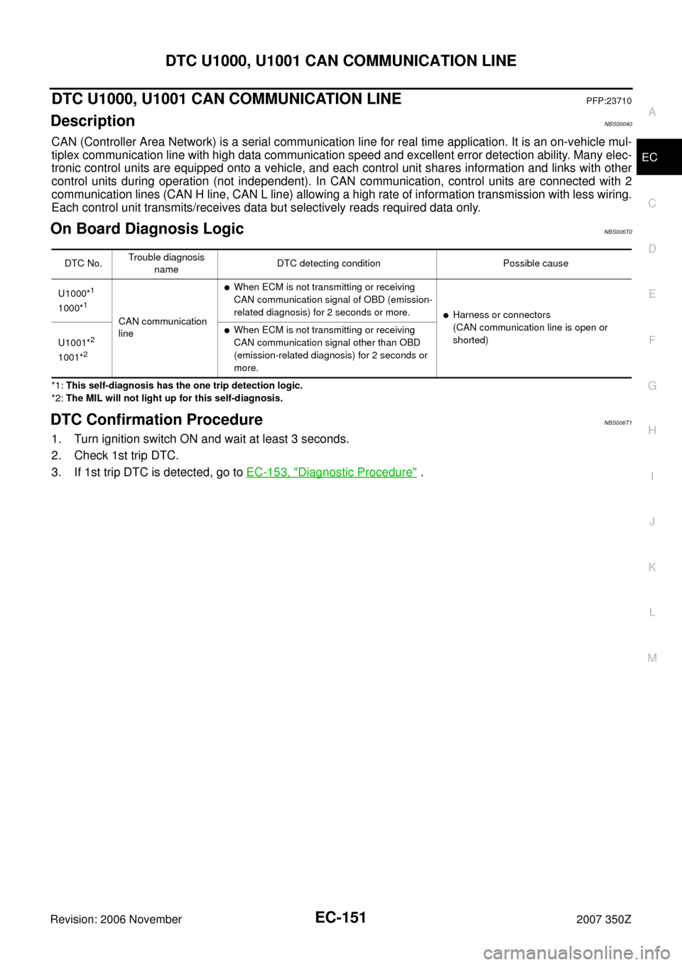
DTC U1000, U1001 CAN COMMUNICATION LINEPFP:23710
DescriptionNBS00040
CAN (Controller Area Network) is a serial communication line for real time application. It is an on-vehicle mul-
tiplex communication line with high data communication speed and excellent error detection ability. Many elec-
tronic control units are equipped onto a vehicle, and each control unit shares information and links with other
control units during operation (not independent). In CAN communication, control units are connected with 2
communication lines (CAN H line, CAN L line) allowing a high rate of information transmission with less wiring.
Each control unit transmits/receives data but selectively reads required data only.
On Board Diagnosis LogicNBS006T0
*1: This self-diagnosis has the one trip detection logic.
*2: The MIL will not light up for this self-diagnosis.
DTC Confirmation ProcedureNBS006T1
1. Turn ignition switch ON and wait at least 3 seconds.
2. Check 1st trip DTC.
3. If 1st trip DTC is detected, go to EC-153, "
Diagnostic Procedure" .
DTC No.Trouble diagnosis
nameDTC detecting condition Possible cause
U1000*
1
1000*1
CAN communication
line
�When ECM is not transmitting or receiving
CAN communication signal of OBD (emission-
related diagnosis) for 2 seconds or more.
�Harness or connectors
(CAN communication line is open or
shorted)
U1001*
2
1001*2
�When ECM is not transmitting or receiving
CAN communication signal other than OBD
(emission-related diagnosis) for 2 seconds or
more.
Page 154 of 720

EC-154
DTC U1010 CAN COMMUNICATION
Revision: 2006 November2007 350Z
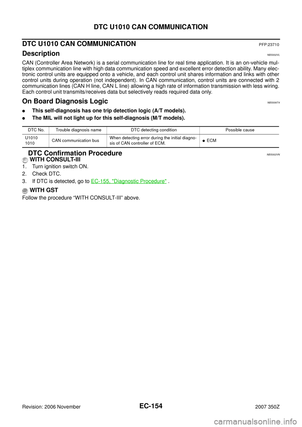
DTC U1010 CAN COMMUNICATIONPFP:23710
DescriptionNBS002VL
CAN (Controller Area Network) is a serial communication line for real time application. It is an on-vehicle mul-
tiplex communication line with high data communication speed and excellent error detection ability. Many elec-
tronic control units are equipped onto a vehicle, and each control unit shares information and links with other
control units during operation (not independent). In CAN communication, control units are connected with 2
communication lines (CAN H line, CAN L line) allowing a high rate of information transmission with less wiring.
Each control unit transmits/receives data but selectively reads required data only.
On Board Diagnosis LogicNBS006T4
�This self-diagnosis has one trip detection logic (A/T models).
�The MIL will not light up for this self-diagnosis (M/T models).
DTC Confirmation ProcedureNBS002VN
WITH CONSULT-III
1. Turn ignition switch ON.
2. Check DTC.
3. If DTC is detected, go to EC-155, "
Diagnostic Procedure" .
WITH GST
Follow the procedure “WITH CONSULT-III” above.
DTC No. Trouble diagnosis name DTC detecting condition Possible cause
U1010
1010CAN communication busWhen detecting error during the initial diagno-
sis of CAN controller of ECM.
�ECM
Page 625 of 720

DTC P1574 ASCD VEHICLE SPEED SENSOR
EC-625
C
D
E
F
G
H
I
J
K
L
MA
EC
Revision: 2006 November2007 350Z
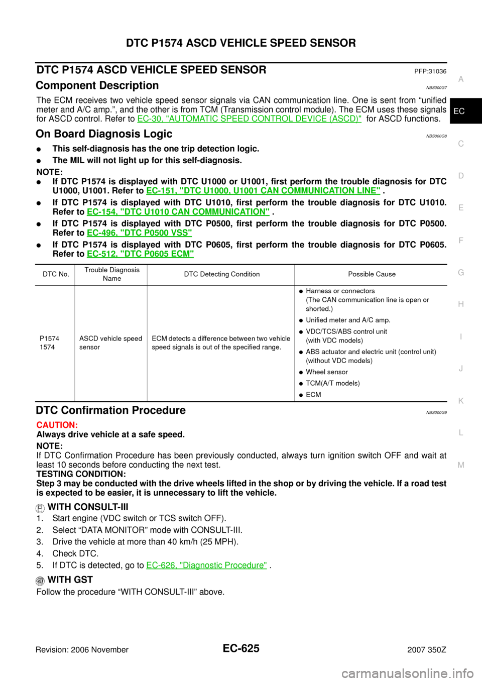
DTC P1574 ASCD VEHICLE SPEED SENSORPFP:31036
Component DescriptionNBS000G7
The ECM receives two vehicle speed sensor signals via CAN communication line. One is sent from “unified
meter and A/C amp.”, and the other is from TCM (Transmission control module). The ECM uses these signals
for ASCD control. Refer to EC-30, "
AUTOMATIC SPEED CONTROL DEVICE (ASCD)" for ASCD functions.
On Board Diagnosis LogicNBS000G8
�This self-diagnosis has the one trip detection logic.
�The MIL will not light up for this self-diagnosis.
NOTE:
�If DTC P1574 is displayed with DTC U1000 or U1001, first perform the trouble diagnosis for DTC
U1000, U1001. Refer to EC-151, "
DTC U1000, U1001 CAN COMMUNICATION LINE" .
�If DTC P1574 is displayed with DTC U1010, first perform the trouble diagnosis for DTC U1010.
Refer to EC-154, "
DTC U1010 CAN COMMUNICATION" .
�If DTC P1574 is displayed with DTC P0500, first perform the trouble diagnosis for DTC P0500.
Refer to EC-496, "
DTC P0500 VSS"
�If DTC P1574 is displayed with DTC P0605, first perform the trouble diagnosis for DTC P0605.
Refer to EC-512, "
DTC P0605 ECM"
DTC Confirmation ProcedureNBS000G9
CAUTION:
Always drive vehicle at a safe speed.
NOTE:
If DTC Confirmation Procedure has been previously conducted, always turn ignition switch OFF and wait at
least 10 seconds before conducting the next test.
TESTING CONDITION:
Step 3 may be conducted with the drive wheels lifted in the shop or by driving the vehicle. If a road test
is expected to be easier, it is unnecessary to lift the vehicle.
WITH CONSULT-III
1. Start engine (VDC switch or TCS switch OFF).
2. Select “DATA MONITOR” mode with CONSULT-III.
3. Drive the vehicle at more than 40 km/h (25 MPH).
4. Check DTC.
5. If DTC is detected, go to EC-626, "
Diagnostic Procedure" .
WITH GST
Follow the procedure “WITH CONSULT-III” above.
DTC No.Trouble Diagnosis
NameDTC Detecting Condition Possible Cause
P1574
1574ASCD vehicle speed
sensorECM detects a difference between two vehicle
speed signals is out of the specified range.
�Harness or connectors
(The CAN communication line is open or
shorted.)
�Unified meter and A/C amp.
�VDC/TCS/ABS control unit
(with VDC models)
�ABS actuator and electric unit (control unit)
(without VDC models)
�Wheel sensor
�TCM(A/T models)
�ECM