Page 74 of 720
EC-74
BASIC SERVICE PROCEDURE
Revision: 2006 November2007 350Z
11 . PERFORM ACCELERATOR PEDAL RELEASED POSITION LEARNING
1. Stop engine.
2. Perform EC-77, "
Accelerator Pedal Released Position Learning" .
>> GO TO 12.
12. PERFORM THROTTLE VALVE CLOSED POSITION LEARNING
Perform EC-77, "
Throttle Valve Closed Position Learning" .
>> GO TO 13.
13. PERFORM IDLE AIR VOLUME LEARNING
Refer to EC-77, "
Idle Air Volume Learning" .
Is Idle Air Volume Learning carried out successfully?
Ye s o r N o
Yes >> GO TO 14.
No >> 1. Follow the instruction of Idle Air Volume Learning.
2. GO TO 4.
14. CHECK TARGET IDLE SPEED AGAIN
With CONSULT-III
1. Start engine and warm it up to normal operating temperature.
2. Read idle speed in “DATA MONITOR” mode with CONSULT-III.
Refer to EC-76, "
IDLE SPEED" .
Without CONSULT-III
1. Start engine and warm it up to normal operating temperature.
2. Check idle speed. Refer to EC-76, "
IDLE SPEED" .
OK or NG
OK >> GO TO 15.
NG >> GO TO 17.
15. CHECK IGNITION TIMING AGAIN
1. Run engine at idle.
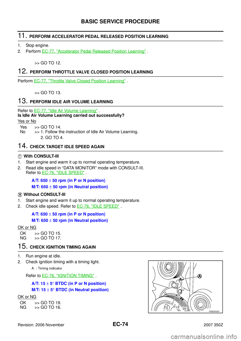
2. Check ignition timing with a timing light.
Refer to EC-76, "
IGNITION TIMING" .
OK or NG
OK >> GO TO 19.
NG >> GO TO 16.A/T: 650 ± 50 rpm (in P or N position)
M/T: 650 ± 50 rpm (in Neutral position)
A/T: 650 ± 50 rpm (in P or N position)
M/T: 650 ± 50 rpm (in Neutral position)
A : Timing indicator
A/T: 15 ± 5° BTDC (in P or N position)
M/T: 15 ± 5° BTDC (in Neutral position)
PBIB3530E
Page 76 of 720
EC-76
BASIC SERVICE PROCEDURE
Revision: 2006 November2007 350Z
Idle Speed and Ignition Timing CheckNBS00035
IDLE SPEED
With CONSULT-III
Check idle speed in “DATA MONITOR” mode with CONSULT-III.
With GST
Check idle speed in Service $01 with GST.
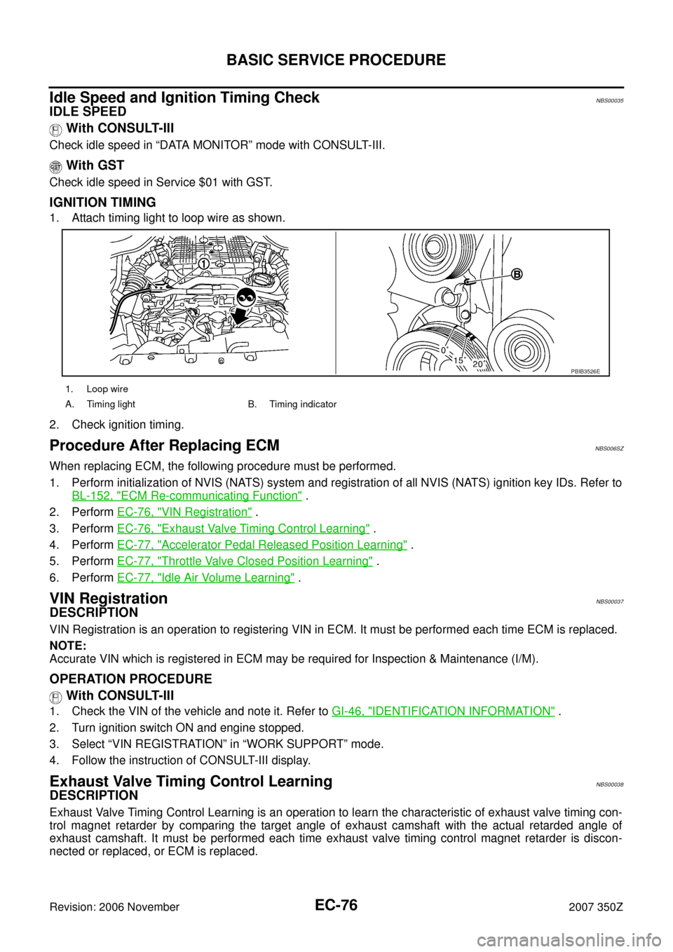
IGNITION TIMING
1. Attach timing light to loop wire as shown.
2. Check ignition timing.
Procedure After Replacing ECMNBS006SZ
When replacing ECM, the following procedure must be performed.
1. Perform initialization of NVIS (NATS) system and registration of all NVIS (NATS) ignition key IDs. Refer to
BL-152, "
ECM Re-communicating Function" .
2. Perform EC-76, "
VIN Registration" .
3. Perform EC-76, "
Exhaust Valve Timing Control Learning" .
4. Perform EC-77, "
Accelerator Pedal Released Position Learning" .
5. Perform EC-77, "
Throttle Valve Closed Position Learning" .
6. Perform EC-77, "
Idle Air Volume Learning" .
VIN RegistrationNBS00037
DESCRIPTION
VIN Registration is an operation to registering VIN in ECM. It must be performed each time ECM is replaced.
NOTE:
Accurate VIN which is registered in ECM may be required for Inspection & Maintenance (I/M).
OPERATION PROCEDURE
With CONSULT-III
1. Check the VIN of the vehicle and note it. Refer to GI-46, "IDENTIFICATION INFORMATION" .
2. Turn ignition switch ON and engine stopped.
3. Select “VIN REGISTRATION” in “WORK SUPPORT” mode.
4. Follow the instruction of CONSULT-III display.
Exhaust Valve Timing Control LearningNBS00038
DESCRIPTION
Exhaust Valve Timing Control Learning is an operation to learn the characteristic of exhaust valve timing con-
trol magnet retarder by comparing the target angle of exhaust camshaft with the actual retarded angle of
exhaust camshaft. It must be performed each time exhaust valve timing control magnet retarder is discon-
nected or replaced, or ECM is replaced.
1. Loop wire
A. Timing light B. Timing indicator
PBIB3526E
Page 419 of 720
DTC P0442 EVAP CONTROL SYSTEM
EC-419
C
D
E
F
G
H
I
J
K
L
MA
EC
Revision: 2006 November2007 350Z
6. CHECK FOR EVAP LEAK
With CONSULT-III
1. Turn ignition switch ON.
2. Select “EVAP SYSTEM CLOSE” of “WORK SUPPORT” mode with CONSULT-III.
3. Touch “START” and apply pressure into the EVAP line until the pressure indicator reaches the middle of
the bar graph.
CAUTION:
�Never use compressed air or a high pressure pump.
�Do not exceed 4.12 kPa (0.042 kg/cm2 , 0.6 psi) of pressure in the system.
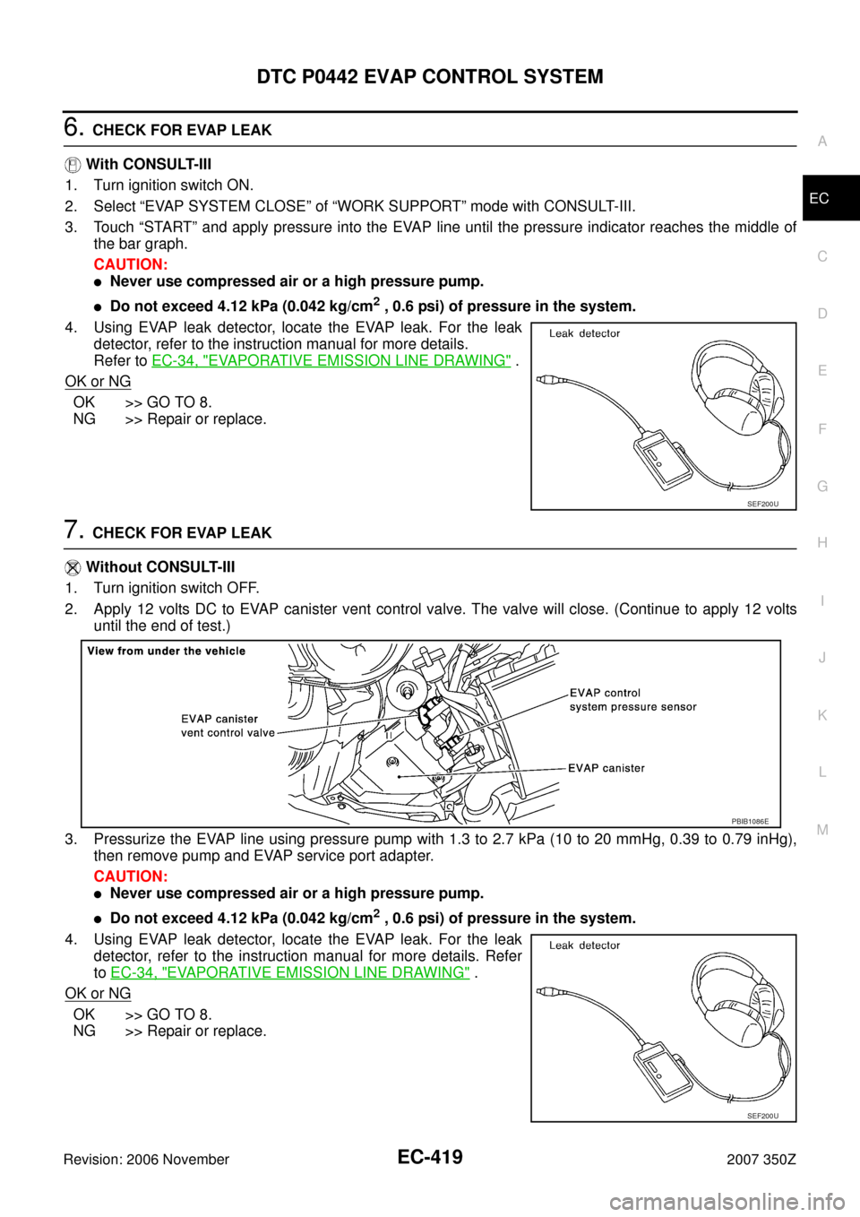
4. Using EVAP leak detector, locate the EVAP leak. For the leak
detector, refer to the instruction manual for more details.
Refer to EC-34, "
EVAPORATIVE EMISSION LINE DRAWING" .
OK or NG
OK >> GO TO 8.
NG >> Repair or replace.
7. CHECK FOR EVAP LEAK
Without CONSULT-III
1. Turn ignition switch OFF.
2. Apply 12 volts DC to EVAP canister vent control valve. The valve will close. (Continue to apply 12 volts
until the end of test.)
3. Pressurize the EVAP line using pressure pump with 1.3 to 2.7 kPa (10 to 20 mmHg, 0.39 to 0.79 inHg),
then remove pump and EVAP service port adapter.
CAUTION:
�Never use compressed air or a high pressure pump.
�Do not exceed 4.12 kPa (0.042 kg/cm2 , 0.6 psi) of pressure in the system.
4. Using EVAP leak detector, locate the EVAP leak. For the leak
detector, refer to the instruction manual for more details. Refer
to EC-34, "
EVAPORATIVE EMISSION LINE DRAWING" .
OK or NG
OK >> GO TO 8.
NG >> Repair or replace.
SEF200U
PBIB1086E
SEF200U
Page 478 of 720
EC-478
DTC P0455 EVAP CONTROL SYSTEM
Revision: 2006 November2007 350Z
7. CHECK EVAP CANISTER VENT CONTROL VALVE
Check the following.
�EVAP canister vent control valve is installed properly.
Refer to EC-37, "
Removal and Installation" .
�EVAP canister vent control valve.
Refer to EC-442, "
Component Inspection" .
OK or NG
OK >> GO TO 8.
NG >> Repair or replace EVAP canister vent control valve and O-ring.
8. INSTALL THE PRESSURE PUMP
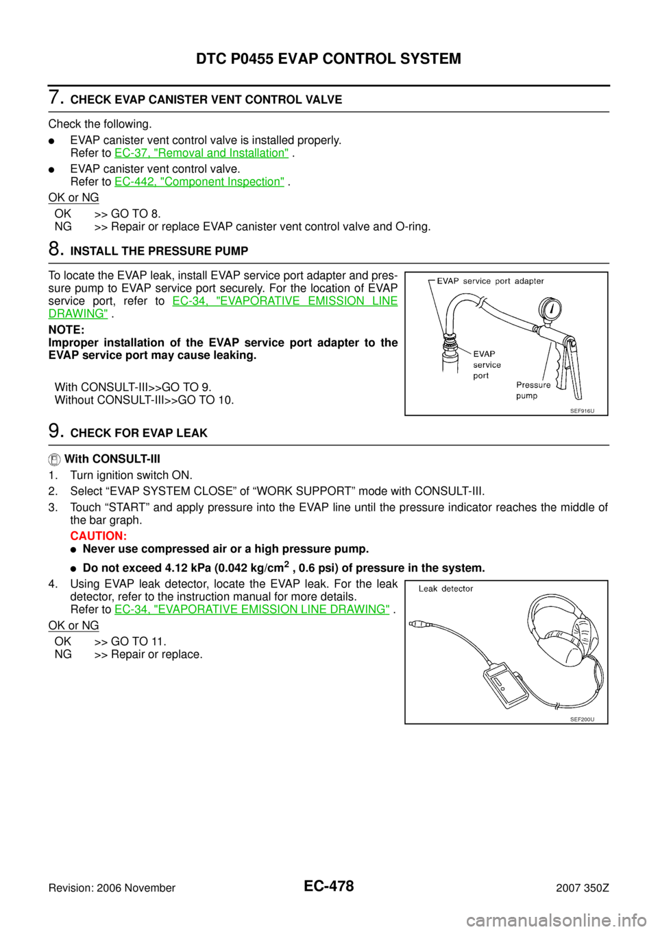
To locate the EVAP leak, install EVAP service port adapter and pres-
sure pump to EVAP service port securely. For the location of EVAP
service port, refer to EC-34, "
EVAPORATIVE EMISSION LINE
DRAWING" .
NOTE:
Improper installation of the EVAP service port adapter to the
EVAP service port may cause leaking.
With CONSULT-III>>GO TO 9.
Without CONSULT-III>>GO TO 10.
9. CHECK FOR EVAP LEAK
With CONSULT-III
1. Turn ignition switch ON.
2. Select “EVAP SYSTEM CLOSE” of “WORK SUPPORT” mode with CONSULT-III.
3. Touch “START” and apply pressure into the EVAP line until the pressure indicator reaches the middle of
the bar graph.
CAUTION:
�Never use compressed air or a high pressure pump.
�Do not exceed 4.12 kPa (0.042 kg/cm2 , 0.6 psi) of pressure in the system.
4. Using EVAP leak detector, locate the EVAP leak. For the leak
detector, refer to the instruction manual for more details.
Refer to EC-34, "
EVAPORATIVE EMISSION LINE DRAWING" .
OK or NG
OK >> GO TO 11.
NG >> Repair or replace.
SEF916U
SEF200U
Page 485 of 720
DTC P0456 EVAP CONTROL SYSTEM
EC-485
C
D
E
F
G
H
I
J
K
L
MA
EC
Revision: 2006 November2007 350Z
4. CHECK FUEL TANK VACUUM RELIEF VALVE
Refer to EC-36, "
FUEL TANK VACUUM RELIEF VALVE (BUILT INTO FUEL FILLER CAP)" .
OK or NG
OK >> GO TO 5.
NG >> Replace fuel filler cap with a genuine one.
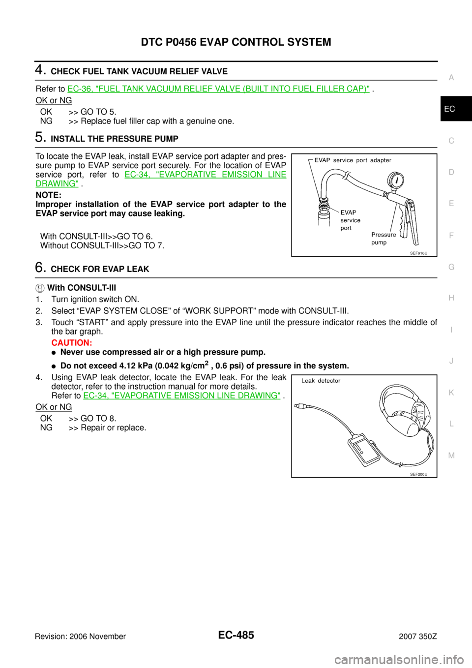
5. INSTALL THE PRESSURE PUMP
To locate the EVAP leak, install EVAP service port adapter and pres-
sure pump to EVAP service port securely. For the location of EVAP
service port, refer to EC-34, "
EVAPORATIVE EMISSION LINE
DRAWING" .
NOTE:
Improper installation of the EVAP service port adapter to the
EVAP service port may cause leaking.
With CONSULT-III>>GO TO 6.
Without CONSULT-III>>GO TO 7.
6. CHECK FOR EVAP LEAK
With CONSULT-III
1. Turn ignition switch ON.
2. Select “EVAP SYSTEM CLOSE” of “WORK SUPPORT” mode with CONSULT-III.
3. Touch “START” and apply pressure into the EVAP line until the pressure indicator reaches the middle of
the bar graph.
CAUTION:
�Never use compressed air or a high pressure pump.
�Do not exceed 4.12 kPa (0.042 kg/cm2 , 0.6 psi) of pressure in the system.
4. Using EVAP leak detector, locate the EVAP leak. For the leak
detector, refer to the instruction manual for more details.
Refer to EC-34, "
EVAPORATIVE EMISSION LINE DRAWING" .
OK or NG
OK >> GO TO 8.
NG >> Repair or replace.
SEF916U
SEF200U