Page 149 of 720

POWER SUPPLY AND GROUND CIRCUIT
EC-149
C
D
E
F
G
H
I
J
K
L
MA
EC
Revision: 2006 November2007 350Z
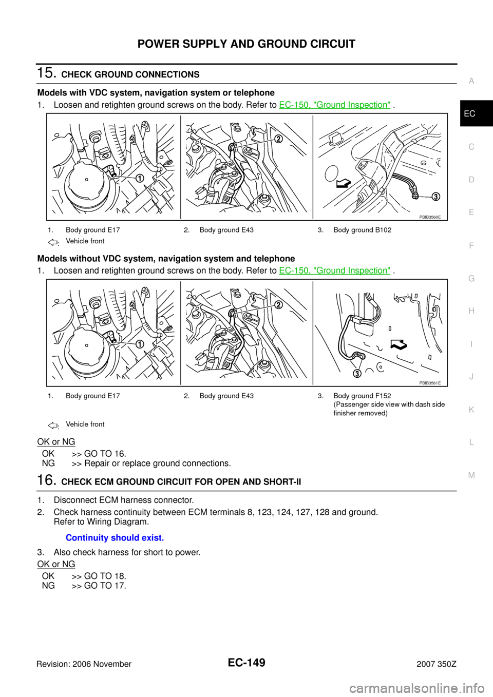
15. CHECK GROUND CONNECTIONS
Models with VDC system, navigation system or telephone
1. Loosen and retighten ground screws on the body. Refer to EC-150, "
Ground Inspection" .
Models without VDC system, navigation system and telephone
1. Loosen and retighten ground screws on the body. Refer to EC-150, "
Ground Inspection" .
OK or NG
OK >> GO TO 16.
NG >> Repair or replace ground connections.
16. CHECK ECM GROUND CIRCUIT FOR OPEN AND SHORT-II
1. Disconnect ECM harness connector.
2. Check harness continuity between ECM terminals 8, 123, 124, 127, 128 and ground.
Refer to Wiring Diagram.
3. Also check harness for short to power.
OK or NG
OK >> GO TO 18.
NG >> GO TO 17.
1. Body ground E17 2. Body ground E43 3. Body ground B102
:Vehicle front
1. Body ground E17 2. Body ground E43 3. Body ground F152
(Passenger side view with dash side
finisher removed)
:Vehicle front
PBIB3560E
PBIB3561E
Continuity should exist.
Page 150 of 720

EC-150
POWER SUPPLY AND GROUND CIRCUIT
Revision: 2006 November2007 350Z
17. DETECT MALFUNCTIONING PART
Check the following.
�Harness connectors F103, B113 (Models with VDC system, navigation system or telephone) or F151
(Models without VDC system, navigation system and telephone)
�Harness or connectors F3, E12
�Harness or connectors M72, F102
�Harness for open or short between ECM and ground.
>> Repair open circuit or short to power in harness or connectors.
18. CHECK INTERMITTENT INCIDENT
Refer to EC-141, "
TROUBLE DIAGNOSIS FOR INTERMITTENT INCIDENT" .
OK or NG
OK >> Replace IPDM E/R. Refer to PG-16, "IPDM E/R (INTELLIGENT POWER DISTRIBUTION MOD-
ULE ENGINE ROOM)" .
NG >> Repair open circuit or short to ground or short to power in harness or connectors.
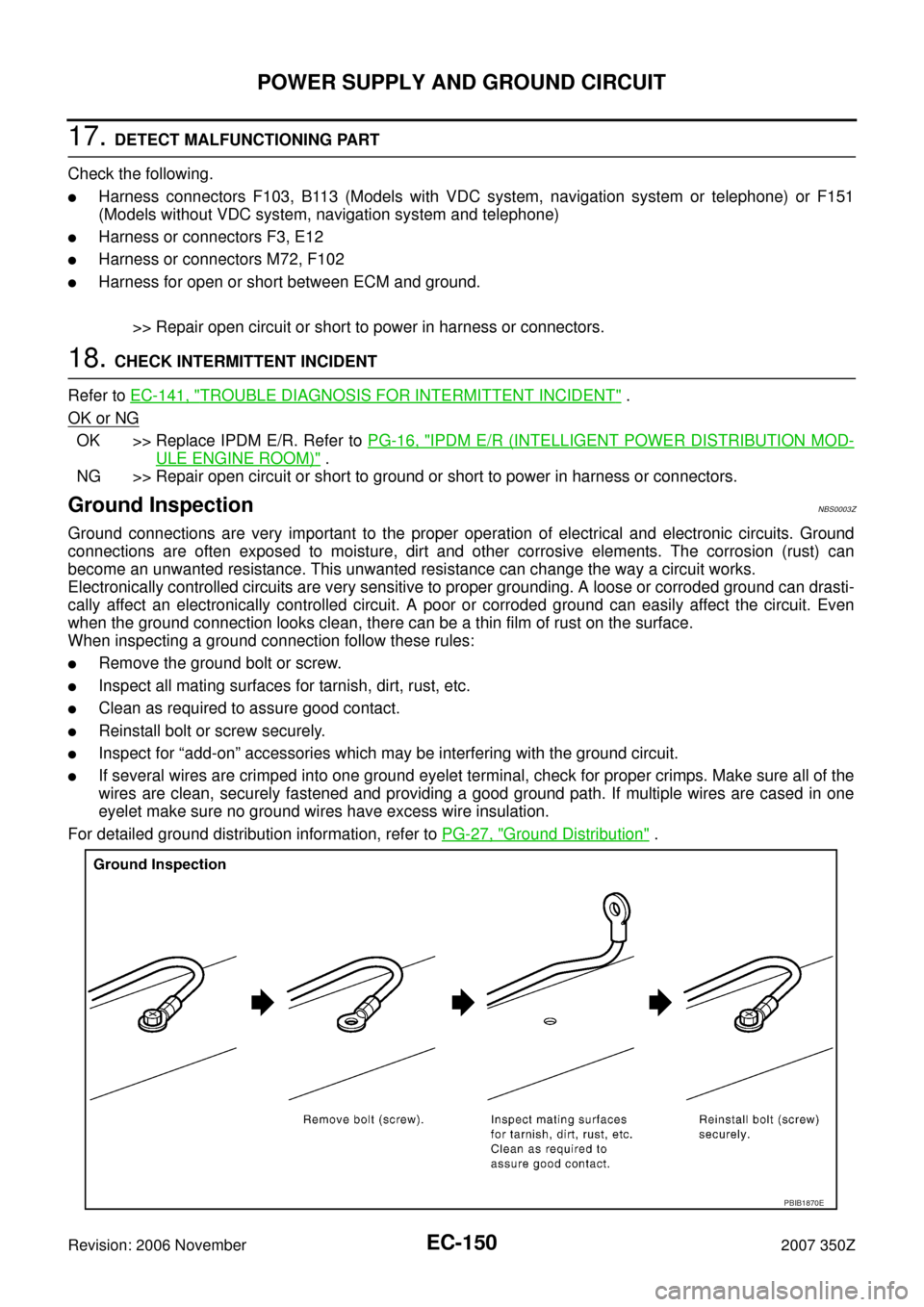
Ground Inspection NBS0003Z
Ground connections are very important to the proper operation of electrical and electronic circuits. Ground
connections are often exposed to moisture, dirt and other corrosive elements. The corrosion (rust) can
become an unwanted resistance. This unwanted resistance can change the way a circuit works.
Electronically controlled circuits are very sensitive to proper grounding. A loose or corroded ground can drasti-
cally affect an electronically controlled circuit. A poor or corroded ground can easily affect the circuit. Even
when the ground connection looks clean, there can be a thin film of rust on the surface.
When inspecting a ground connection follow these rules:
�Remove the ground bolt or screw.
�Inspect all mating surfaces for tarnish, dirt, rust, etc.
�Clean as required to assure good contact.
�Reinstall bolt or screw securely.
�Inspect for “add-on” accessories which may be interfering with the ground circuit.
�If several wires are crimped into one ground eyelet terminal, check for proper crimps. Make sure all of the
wires are clean, securely fastened and providing a good ground path. If multiple wires are cased in one
eyelet make sure no ground wires have excess wire insulation.
For detailed ground distribution information, refer to PG-27, "
Ground Distribution" .
PBIB1870E
Page 151 of 720

DTC U1000, U1001 CAN COMMUNICATION LINE
EC-151
C
D
E
F
G
H
I
J
K
L
MA
EC
Revision: 2006 November2007 350Z
DTC U1000, U1001 CAN COMMUNICATION LINEPFP:23710
DescriptionNBS00040
CAN (Controller Area Network) is a serial communication line for real time application. It is an on-vehicle mul-
tiplex communication line with high data communication speed and excellent error detection ability. Many elec-
tronic control units are equipped onto a vehicle, and each control unit shares information and links with other
control units during operation (not independent). In CAN communication, control units are connected with 2
communication lines (CAN H line, CAN L line) allowing a high rate of information transmission with less wiring.
Each control unit transmits/receives data but selectively reads required data only.
On Board Diagnosis LogicNBS006T0
*1: This self-diagnosis has the one trip detection logic.
*2: The MIL will not light up for this self-diagnosis.
DTC Confirmation ProcedureNBS006T1
1. Turn ignition switch ON and wait at least 3 seconds.
2. Check 1st trip DTC.
3. If 1st trip DTC is detected, go to EC-153, "
Diagnostic Procedure" .
DTC No.Trouble diagnosis
nameDTC detecting condition Possible cause
U1000*
1
1000*1
CAN communication
line
�When ECM is not transmitting or receiving
CAN communication signal of OBD (emission-
related diagnosis) for 2 seconds or more.
�Harness or connectors
(CAN communication line is open or
shorted)
U1001*
2
1001*2
�When ECM is not transmitting or receiving
CAN communication signal other than OBD
(emission-related diagnosis) for 2 seconds or
more.
Page 152 of 720
EC-152
DTC U1000, U1001 CAN COMMUNICATION LINE
Revision: 2006 November2007 350Z
Wiring DiagramNBS006T2
TBWT1616E
Page 153 of 720
DTC U1000, U1001 CAN COMMUNICATION LINE
EC-153
C
D
E
F
G
H
I
J
K
L
MA
EC
Revision: 2006 November2007 350Z
Diagnostic ProcedureNBS006T3
Go to LAN-48, "CAN System Specification Chart" .
Page 154 of 720

EC-154
DTC U1010 CAN COMMUNICATION
Revision: 2006 November2007 350Z
DTC U1010 CAN COMMUNICATIONPFP:23710
DescriptionNBS002VL
CAN (Controller Area Network) is a serial communication line for real time application. It is an on-vehicle mul-
tiplex communication line with high data communication speed and excellent error detection ability. Many elec-
tronic control units are equipped onto a vehicle, and each control unit shares information and links with other
control units during operation (not independent). In CAN communication, control units are connected with 2
communication lines (CAN H line, CAN L line) allowing a high rate of information transmission with less wiring.
Each control unit transmits/receives data but selectively reads required data only.
On Board Diagnosis LogicNBS006T4
�This self-diagnosis has one trip detection logic (A/T models).
�The MIL will not light up for this self-diagnosis (M/T models).
DTC Confirmation ProcedureNBS002VN
WITH CONSULT-III
1. Turn ignition switch ON.
2. Check DTC.
3. If DTC is detected, go to EC-155, "
Diagnostic Procedure" .
WITH GST
Follow the procedure “WITH CONSULT-III” above.
DTC No. Trouble diagnosis name DTC detecting condition Possible cause
U1010
1010CAN communication busWhen detecting error during the initial diagno-
sis of CAN controller of ECM.
�ECM
Page 155 of 720

DTC U1010 CAN COMMUNICATION
EC-155
C
D
E
F
G
H
I
J
K
L
MA
EC
Revision: 2006 November2007 350Z
Diagnostic ProcedureNBS002VO
1. INSPECTION START
With CONSULT-III
1. Turn ignition switch ON.
2. Select “SELF-DIAG RESULTS” mode with CONSULT-III.
3. Touch “ERASE”.
4.Perform DTC Confirmation Procedure.
See EC-154, "
DTC Confirmation Procedure" .
5. Is the DTC U1010 displayed again?
With GST
1. Turn ignition switch ON.
2. Select Service $04 with GST.
3.Perform DTC Confirmation Procedure.
See EC-154, "
DTC Confirmation Procedure" .
4. Is the DTC U1010 displayed again?
Ye s o r N o
Ye s > > G O T O 2 .
No >>INSPECTION END
2. REPLACE ECM
1. Replace ECM.
2. Perform initialization of NVIS (NATS) system and registration of all NVIS (NATS) ignition key IDs. Refer to
BL-152, "
ECM Re-communicating Function" .
3. Perform EC-76, "
VIN Registration" .
4. Perform EC-76, "
Exhaust Valve Timing Control Learning"
5. Perform EC-77, "Accelerator Pedal Released Position Learning" .
6. Perform EC-77, "
Throttle Valve Closed Position Learning" .
7. Perform EC-77, "
Idle Air Volume Learning" .
>>INSPECTION END
Page 156 of 720

EC-156
DTC P0011, P0021 IVT CONTROL
Revision: 2006 November2007 350Z
DTC P0011, P0021 IVT CONTROLPFP:23796
DescriptionNBS00045
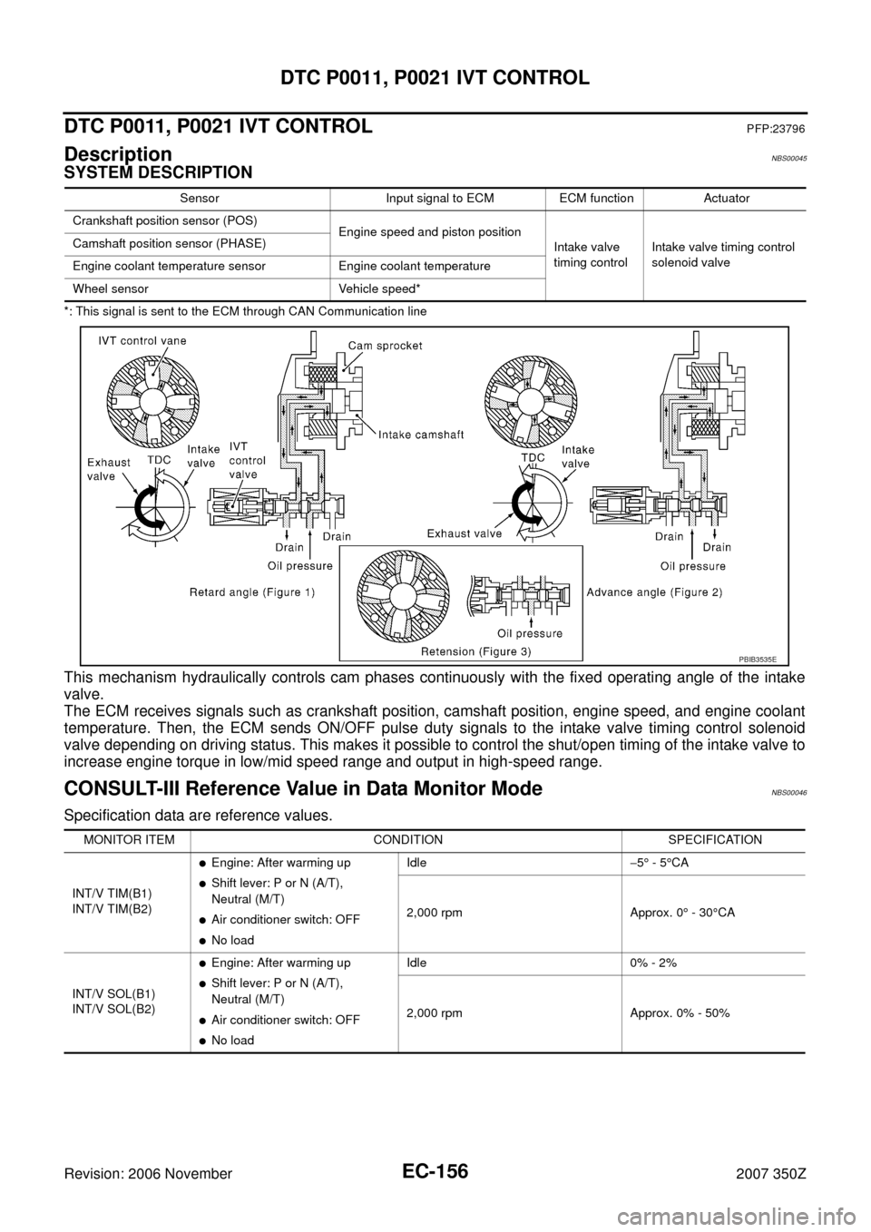
SYSTEM DESCRIPTION
*: This signal is sent to the ECM through CAN Communication line
This mechanism hydraulically controls cam phases continuously with the fixed operating angle of the intake
valve.
The ECM receives signals such as crankshaft position, camshaft position, engine speed, and engine coolant
temperature. Then, the ECM sends ON/OFF pulse duty signals to the intake valve timing control solenoid
valve depending on driving status. This makes it possible to control the shut/open timing of the intake valve to
increase engine torque in low/mid speed range and output in high-speed range.
CONSULT-III Reference Value in Data Monitor ModeNBS00046
Specification data are reference values.
Sensor Input signal to ECM ECM function Actuator
Crankshaft position sensor (POS)
Engine speed and piston position
Intake valve
timing controlIntake valve timing control
solenoid valve Camshaft position sensor (PHASE)
Engine coolant temperature sensor Engine coolant temperature
Wheel sensor Vehicle speed*
PBIB3535E
MONITOR ITEM CONDITION SPECIFICATION
INT/V TIM(B1)
INT/V TIM(B2)
�Engine: After warming up
�Shift lever: P or N (A/T),
Neutral (M/T)
�Air conditioner switch: OFF
�No loadIdle−5° - 5°CA
2,000 rpm Approx. 0° - 30°CA
INT/V SOL(B1)
INT/V SOL(B2)
�Engine: After warming up
�Shift lever: P or N (A/T),
Neutral (M/T)
�Air conditioner switch: OFF
�No loadIdle 0% - 2%
2,000 rpm Approx. 0% - 50%