Page 661 of 720
DTC P2A00, P2A03 A/F SENSOR 1
EC-661
C
D
E
F
G
H
I
J
K
L
MA
EC
Revision: 2006 November2007 350Z
Wiring Diagram NBS000EI
BANK 1
TBWT1632E
Page 669 of 720

DTC P2A00, P2A03 A/F SENSOR 1
EC-669
C
D
E
F
G
H
I
J
K
L
MA
EC
Revision: 2006 November2007 350Z
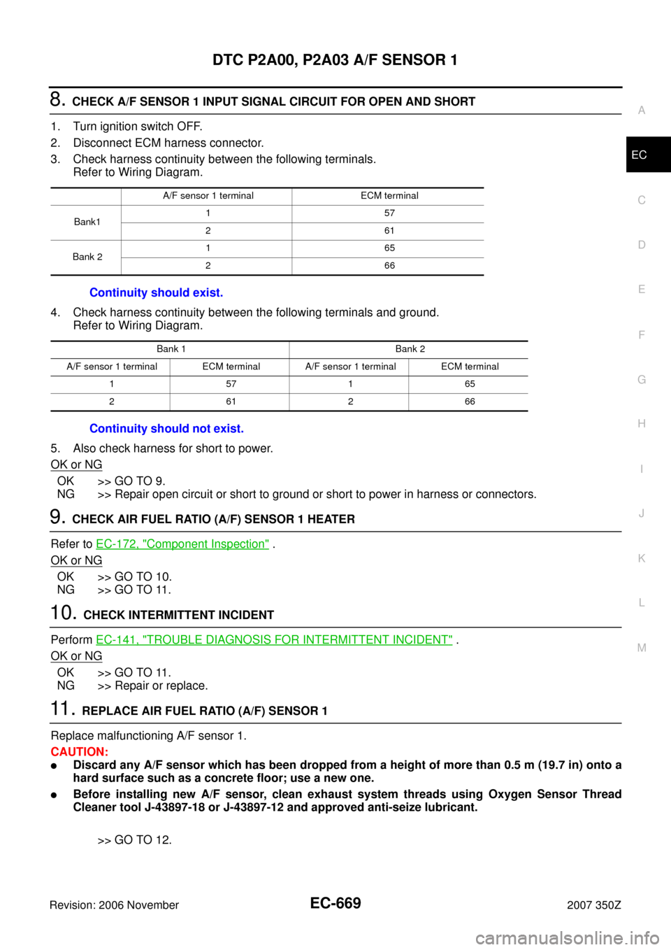
8. CHECK A/F SENSOR 1 INPUT SIGNAL CIRCUIT FOR OPEN AND SHORT
1. Turn ignition switch OFF.
2. Disconnect ECM harness connector.
3. Check harness continuity between the following terminals.
Refer to Wiring Diagram.
4. Check harness continuity between the following terminals and ground.
Refer to Wiring Diagram.
5. Also check harness for short to power.
OK or NG
OK >> GO TO 9.
NG >> Repair open circuit or short to ground or short to power in harness or connectors.
9. CHECK AIR FUEL RATIO (A/F) SENSOR 1 HEATER
Refer to EC-172, "
Component Inspection" .
OK or NG
OK >> GO TO 10.
NG >> GO TO 11.
10. CHECK INTERMITTENT INCIDENT
Perform EC-141, "
TROUBLE DIAGNOSIS FOR INTERMITTENT INCIDENT" .
OK or NG
OK >> GO TO 11.
NG >> Repair or replace.
11 . REPLACE AIR FUEL RATIO (A/F) SENSOR 1
Replace malfunctioning A/F sensor 1.
CAUTION:
�Discard any A/F sensor which has been dropped from a height of more than 0.5 m (19.7 in) onto a
hard surface such as a concrete floor; use a new one.
�Before installing new A/F sensor, clean exhaust system threads using Oxygen Sensor Thread
Cleaner tool J-43897-18 or J-43897-12 and approved anti-seize lubricant.
>> GO TO 12.
A/F sensor 1 terminal ECM terminal
Bank1157
261
Bank 2165
266
Continuity should exist.
Bank 1 Bank 2
A/F sensor 1 terminal ECM terminal A/F sensor 1 terminal ECM terminal
157165
261266
Continuity should not exist.
Page 672 of 720
EC-672
ASCD BRAKE SWITCH
Revision: 2006 November2007 350Z
Wiring DiagramNBS000IB
A/T MODELS
TBWT1675E
Page 676 of 720

EC-676
ASCD BRAKE SWITCH
Revision: 2006 November2007 350Z
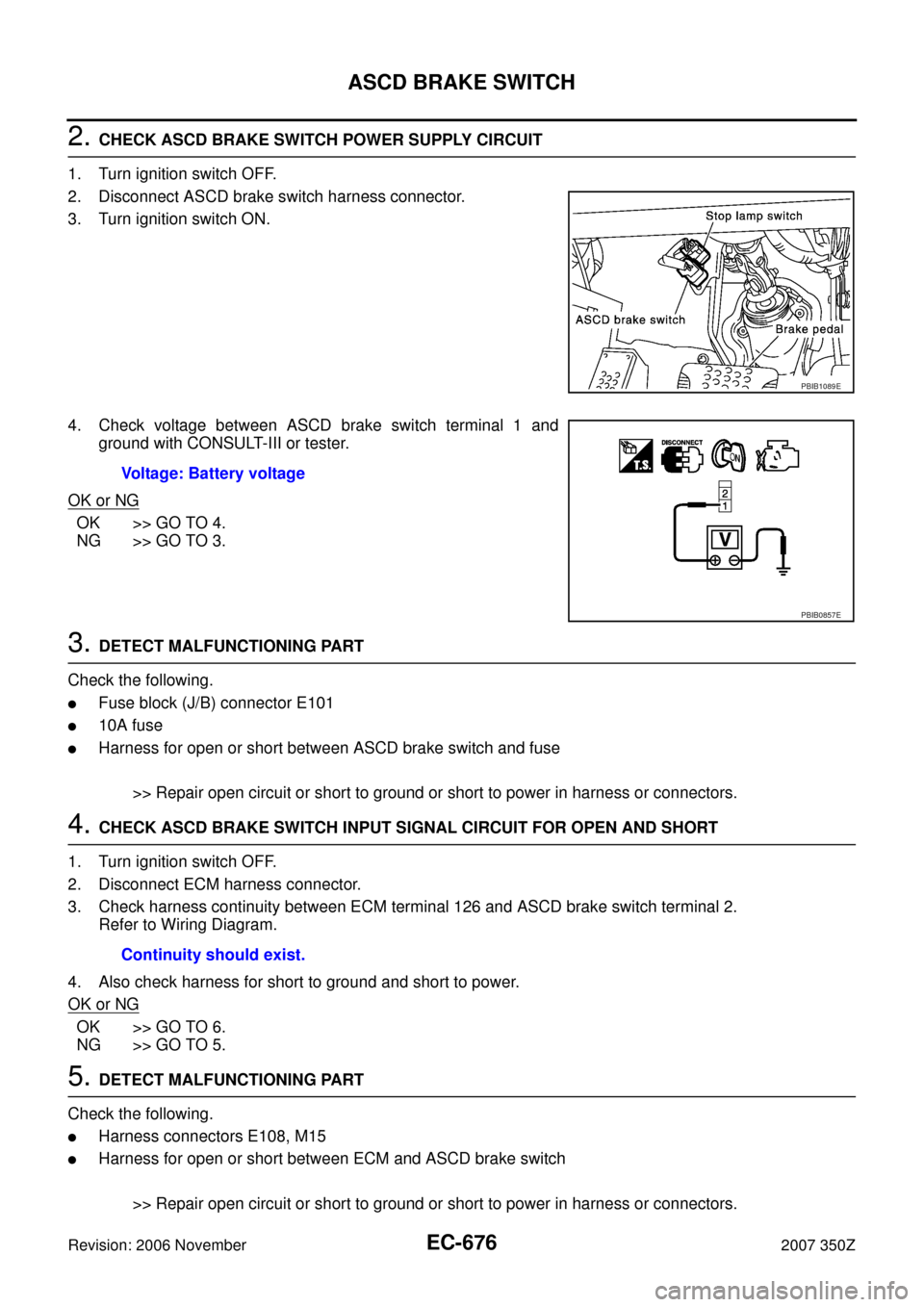
2. CHECK ASCD BRAKE SWITCH POWER SUPPLY CIRCUIT
1. Turn ignition switch OFF.
2. Disconnect ASCD brake switch harness connector.
3. Turn ignition switch ON.
4. Check voltage between ASCD brake switch terminal 1 and
ground with CONSULT-III or tester.
OK or NG
OK >> GO TO 4.
NG >> GO TO 3.
3. DETECT MALFUNCTIONING PART
Check the following.
�Fuse block (J/B) connector E101
�10A fuse
�Harness for open or short between ASCD brake switch and fuse
>> Repair open circuit or short to ground or short to power in harness or connectors.
4. CHECK ASCD BRAKE SWITCH INPUT SIGNAL CIRCUIT FOR OPEN AND SHORT
1. Turn ignition switch OFF.
2. Disconnect ECM harness connector.
3. Check harness continuity between ECM terminal 126 and ASCD brake switch terminal 2.
Refer to Wiring Diagram.
4. Also check harness for short to ground and short to power.
OK or NG
OK >> GO TO 6.
NG >> GO TO 5.
5. DETECT MALFUNCTIONING PART
Check the following.
�Harness connectors E108, M15
�Harness for open or short between ECM and ASCD brake switch
>> Repair open circuit or short to ground or short to power in harness or connectors.
PBIB1089E
Voltage: Battery voltage
PBIB0857E
Continuity should exist.
Page 679 of 720

ASCD BRAKE SWITCH
EC-679
C
D
E
F
G
H
I
J
K
L
MA
EC
Revision: 2006 November2007 350Z
4. DETECT MALFUNCTIONING PART
Check the following.
�Fuse block (J/B) connector E101
�10A fuse
�Harness for open or short between ASCD brake switch and fuse
>> Repair open circuit or short to ground or short to power in harness or connectors.
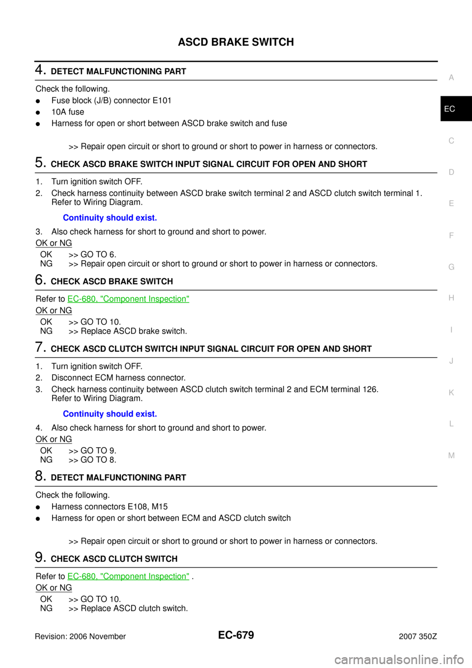
5. CHECK ASCD BRAKE SWITCH INPUT SIGNAL CIRCUIT FOR OPEN AND SHORT
1. Turn ignition switch OFF.
2. Check harness continuity between ASCD brake switch terminal 2 and ASCD clutch switch terminal 1.
Refer to Wiring Diagram.
3. Also check harness for short to ground and short to power.
OK or NG
OK >> GO TO 6.
NG >> Repair open circuit or short to ground or short to power in harness or connectors.
6. CHECK ASCD BRAKE SWITCH
Refer to EC-680, "
Component Inspection"
OK or NG
OK >> GO TO 10.
NG >> Replace ASCD brake switch.
7. CHECK ASCD CLUTCH SWITCH INPUT SIGNAL CIRCUIT FOR OPEN AND SHORT
1. Turn ignition switch OFF.
2. Disconnect ECM harness connector.
3. Check harness continuity between ASCD clutch switch terminal 2 and ECM terminal 126.
Refer to Wiring Diagram.
4. Also check harness for short to ground and short to power.
OK or NG
OK >> GO TO 9.
NG >> GO TO 8.
8. DETECT MALFUNCTIONING PART
Check the following.
�Harness connectors E108, M15
�Harness for open or short between ECM and ASCD clutch switch
>> Repair open circuit or short to ground or short to power in harness or connectors.
9. CHECK ASCD CLUTCH SWITCH
Refer to EC-680, "
Component Inspection" .
OK or NG
OK >> GO TO 10.
NG >> Replace ASCD clutch switch.Continuity should exist.
Continuity should exist.
Page 682 of 720
EC-682
ASCD INDICATOR
Revision: 2006 November2007 350Z
Wiring DiagramNBS000IG
TBWT1677E
Page 687 of 720
FUEL INJECTOR
EC-687
C
D
E
F
G
H
I
J
K
L
MA
EC
Revision: 2006 November2007 350Z
Wiring DiagramNBS000HS
TBWT1678E
Page 689 of 720

FUEL INJECTOR
EC-689
C
D
E
F
G
H
I
J
K
L
MA
EC
Revision: 2006 November2007 350Z
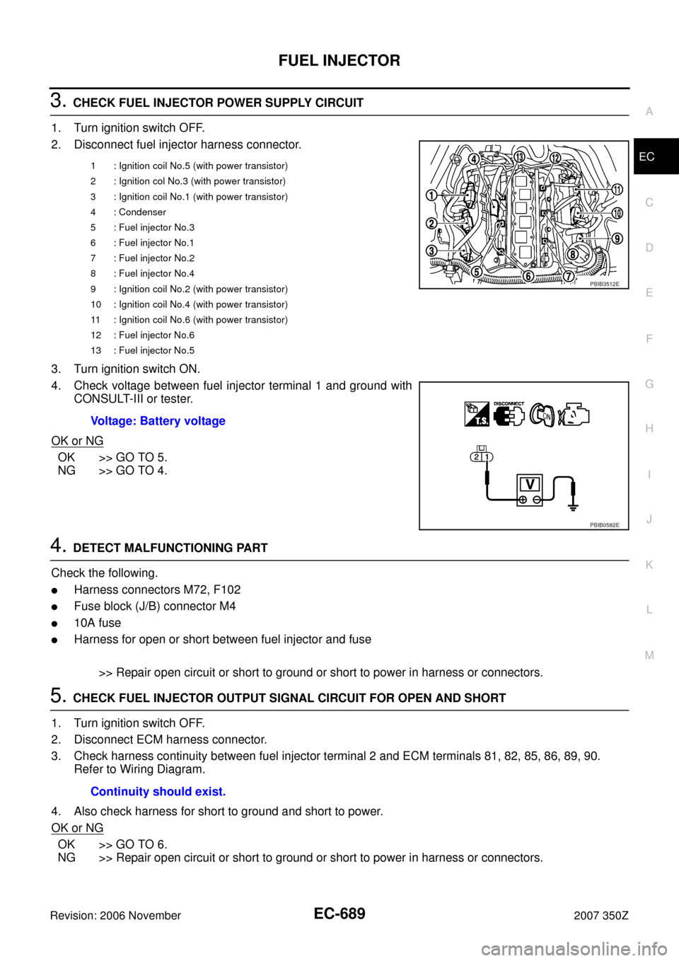
3. CHECK FUEL INJECTOR POWER SUPPLY CIRCUIT
1. Turn ignition switch OFF.
2. Disconnect fuel injector harness connector.
3. Turn ignition switch ON.
4. Check voltage between fuel injector terminal 1 and ground with
CONSULT-III or tester.
OK or NG
OK >> GO TO 5.
NG >> GO TO 4.
4. DETECT MALFUNCTIONING PART
Check the following.
�Harness connectors M72, F102
�Fuse block (J/B) connector M4
�10A fuse
�Harness for open or short between fuel injector and fuse
>> Repair open circuit or short to ground or short to power in harness or connectors.
5. CHECK FUEL INJECTOR OUTPUT SIGNAL CIRCUIT FOR OPEN AND SHORT
1. Turn ignition switch OFF.
2. Disconnect ECM harness connector.
3. Check harness continuity between fuel injector terminal 2 and ECM terminals 81, 82, 85, 86, 89, 90.
Refer to Wiring Diagram.
4. Also check harness for short to ground and short to power.
OK or NG
OK >> GO TO 6.
NG >> Repair open circuit or short to ground or short to power in harness or connectors.
1 : Ignition coil No.5 (with power transistor)
2 : Ignition col No.3 (with power transistor)
3 : Ignition coil No.1 (with power transistor)
4 : Condenser
5 : Fuel injector No.3
6 : Fuel injector No.1
7 : Fuel injector No.2
8 : Fuel injector No.4
9 : Ignition coil No.2 (with power transistor)
10 : Ignition coil No.4 (with power transistor)
11 : Ignition coil No.6 (with power transistor)
12 : Fuel injector No.6
13 : Fuel injector No.5
Voltage: Battery voltage
PBIB3512E
PBIB0582E
Continuity should exist.