Page 572 of 720
EC-572
DTC P1236, P2118 THROTTLE CONTROL MOTOR
Revision: 2006 November2007 350Z
Wiring DiagramNBS000CJ
BANK 1
TBWT1668E
Page 573 of 720

DTC P1236, P2118 THROTTLE CONTROL MOTOR
EC-573
C
D
E
F
G
H
I
J
K
L
MA
EC
Revision: 2006 November2007 350Z
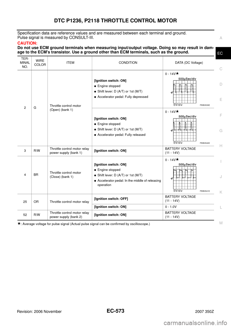
Specification data are reference values and are measured between each terminal and ground.
Pulse signal is measured by CONSULT-III.
CAUTION:
Do not use ECM ground terminals when measuring input/output voltage. Doing so may result in dam-
age to the ECM's transistor. Use a ground other than ECM terminals, such as the ground.
: Average voltage for pulse signal (Actual pulse signal can be confirmed by oscilloscope.)TER-
MINAL
NO.WIRE
COLORITEM CONDITION DATA (DC Voltage)
2GThrottle control motor
(Open) (bank 1)[Ignition switch: ON]
�Engine stopped
�Shift lever: D (A/T) or 1st (M/T)
�Accelerator pedal: Fully depressed0 - 14V
[Ignition switch: ON]
�Engine stopped
�Shift lever: D (A/T) or 1st (M/T)
�Accelerator pedal: Fully released0 - 14V
3R/WThrottle control motor relay
power supply (bank 1)[Ignition switch: ON]BATTERY VOLTAGE
(11 - 14V)
4BRThrottle control motor
(Close) (bank 1)[Ignition switch: ON]
�Engine stopped
�Shift lever: D (A/T) or 1st (M/T)
�Accelerator pedal: In the middle of releasing
operation0 - 14V
25 OR Throttle control motor relay[Ignition switch: OFF]BATTERY VOLTAGE
(11 - 14V)
[Ignition switch: ON]0 - 1.0V
52 R/WThrottle control motor relay
power supply (bank 2)[Ignition switch: ON]BATTERY VOLTAGE
(11 - 14V)
PBIB3539E
PBIB3540E
PBIB3541E
Page 574 of 720
EC-574
DTC P1236, P2118 THROTTLE CONTROL MOTOR
Revision: 2006 November2007 350Z
BANK 2
TBWT1669E
Page 575 of 720

DTC P1236, P2118 THROTTLE CONTROL MOTOR
EC-575
C
D
E
F
G
H
I
J
K
L
MA
EC
Revision: 2006 November2007 350Z
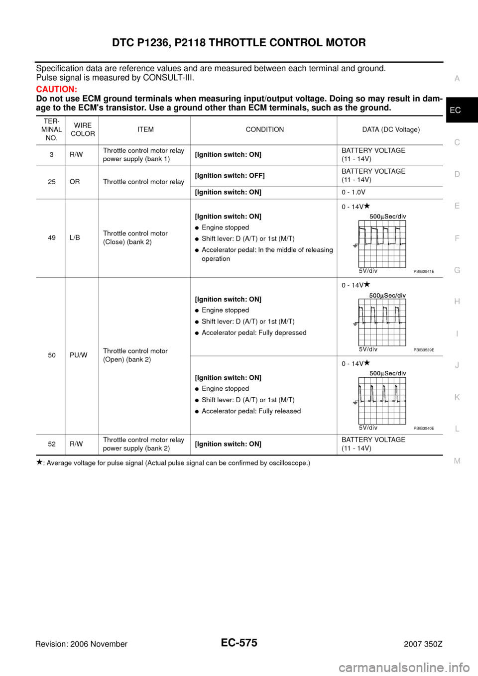
Specification data are reference values and are measured between each terminal and ground.
Pulse signal is measured by CONSULT-III.
CAUTION:
Do not use ECM ground terminals when measuring input/output voltage. Doing so may result in dam-
age to the ECM's transistor. Use a ground other than ECM terminals, such as the ground.
: Average voltage for pulse signal (Actual pulse signal can be confirmed by oscilloscope.)TER-
MINAL
NO.WIRE
COLORITEM CONDITION DATA (DC Voltage)
3R/WThrottle control motor relay
power supply (bank 1)[Ignition switch: ON]BATTERY VOLTAGE
(11 - 14V)
25 OR Throttle control motor relay[Ignition switch: OFF]BATTERY VOLTAGE
(11 - 14V)
[Ignition switch: ON]0 - 1.0V
49 L/BThrottle control motor
(Close) (bank 2)[Ignition switch: ON]
�Engine stopped
�Shift lever: D (A/T) or 1st (M/T)
�Accelerator pedal: In the middle of releasing
operation0 - 14V
50 PU/WThrottle control motor
(Open) (bank 2)[Ignition switch: ON]
�Engine stopped
�Shift lever: D (A/T) or 1st (M/T)
�Accelerator pedal: Fully depressed0 - 14V
[Ignition switch: ON]
�Engine stopped
�Shift lever: D (A/T) or 1st (M/T)
�Accelerator pedal: Fully released0 - 14V
52 R/WThrottle control motor relay
power supply (bank 2)[Ignition switch: ON]BATTERY VOLTAGE
(11 - 14V)
PBIB3541E
PBIB3539E
PBIB3540E
Page 576 of 720
EC-576
DTC P1236, P2118 THROTTLE CONTROL MOTOR
Revision: 2006 November2007 350Z
Diagnostic ProcedureNBS000CK
1. CHECK GROUND CONNECTIONS
Models with VDC system, navigation system or telephone
1. Turn ignition switch OFF.
2. Loosen and retighten ground screws on the body. Refer to EC-150, "
Ground Inspection" .
Models without VDC system, navigation system and telephone
1. Turn ignition switch OFF.
2. Loosen and retighten ground screws on the body. Refer to EC-150, "
Ground Inspection" .
OK or NG
OK >> GO TO 2.
NG >> Repair or replace ground connections.
1. Body ground E17 2. Body ground E43 3. Body ground B102
:Vehicle front
1. Body ground E17 2. Body ground E43 3. Body ground F152
(Passenger side view with dash side
finisher removed)
:Vehicle front
PBIB3560E
PBIB3561E
Page 577 of 720

DTC P1236, P2118 THROTTLE CONTROL MOTOR
EC-577
C
D
E
F
G
H
I
J
K
L
MA
EC
Revision: 2006 November2007 350Z
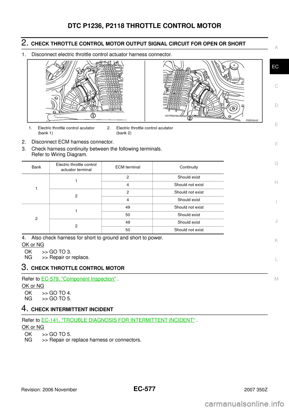
2. CHECK THROTTLE CONTROL MOTOR OUTPUT SIGNAL CIRCUIT FOR OPEN OR SHORT
1. Disconnect electric throttle control actuator harness connector.
2. Disconnect ECM harness connector.
3. Check harness continuity between the following terminals.
Refer to Wiring Diagram.
4. Also check harness for short to ground and short to power.
OK or NG
OK >> GO TO 3.
NG >> Repair or replace.
3. CHECK THROTTLE CONTROL MOTOR
Refer to EC-579, "
Component Inspection" .
OK or NG
OK >> GO TO 4.
NG >> GO TO 5.
4. CHECK INTERMITTENT INCIDENT
Refer to EC-141, "
TROUBLE DIAGNOSIS FOR INTERMITTENT INCIDENT" .
OK or NG
OK >> GO TO 5.
NG >> Repair or replace harness or connectors.
1. Electric throttle control acutator
(bank 1)2. Electric throttle control acutator
(bank 2)
BankElectric throttle control
actuator terminalECM terminal Continuity
112 Should exist
4 Should not exist
22 Should not exist
4 Should exist
2149 Should not exist
50 Should exist
249 Should exist
50 Should not exist
PBIB3504E
Page 578 of 720
EC-578
DTC P1236, P2118 THROTTLE CONTROL MOTOR
Revision: 2006 November2007 350Z
5. REPLACE ELECTRIC THROTTLE CONTROL ACTUATOR
1. Replace the electric throttle control actuator.
2. Perform EC-77, "
Throttle Valve Closed Position Learning" .
3. Perform EC-77, "
Idle Air Volume Learning" .
>>INSPECTION END
Page 579 of 720
DTC P1236, P2118 THROTTLE CONTROL MOTOR
EC-579
C
D
E
F
G
H
I
J
K
L
MA
EC
Revision: 2006 November2007 350Z
Component InspectionNBS006V8
THROTTLE CONTROL MOTOR
1. Disconnect electric throttle control actuator harness connector.
2. Check resistance between terminals 1 and 2.
3. If NG, replace electric throttle control actuator and go to next step.
4. Perform EC-77, "
Throttle Valve Closed Position Learning" .
5. Perform EC-77, "
Idle Air Volume Learning" .
Removal and InstallationNBS006V9
ELECTRIC THROTTLE CONTROL ACTUATOR
Refer to EM-17, "INTAKE MANIFOLD COLLECTOR" . Resistance: Approximately 1 - 15 Ω [at 25 °C (77°F)]
PBIB3581E