BRAKE PEDAL
BR-7
C
D
E
G
H
I
J
K
L
MA
B
BR
Revision: 2006 November2007 350Z
BRAKE PEDALPFP:46501
Inspection and AdjustmentNFS00006
PLAY AND CLEARANCE BETWEEN THE BRAKE PEDAL AND FLOOR PANEL WITH PEDAL
DEPRESSED
1. Check the brake pedal free height from the dash lower panel (1).
2. Adjust the height referring to the following specifications.
ADJUSTMENT
1. Loosen the stop lamp switch and ASCD cancel switch by rotat-
ing it counterclockwise by 45°.
2. Loosen the lock nut (A) on the input rod, then rotate the input
rod to set the pedal to the specified height, and tighten the lock
nut (A) to the specified torque. Refer to BR-23, "
Components" .
CAUTION:
Check that the threaded end of the input rod stays inside
the clevis.
3. With the pedal pulled and held by hand, press the stop lamp
switch and ASCD cancel switch until its threaded end contacts
the stopper rubber.
4. With the threaded end of the stop lamp switch contacting the
stopper rubber and ASCD cancel switch, rotate the switch clock-
wise by 45° to secure.
CAUTION:
Make sure that the clearance “C” between the stopper rub-
ber and threaded end of the stop lamp switch and ASCD
cancel switch is within the standard.
5. Check the pedal play.
CAUTION:
Make sure that the stop lamps go off when the pedal is
released.
6. Start the engine to check the brake pedal's depressed height.Brake pedal height “H
1 ” (from dash lower panel top sur-
face)
M/T models : 153.2 – 163.2 mm (6.03 – 6.43 in)
A/T models : 161.5 – 171.5 mm (6.36 – 6.75 in)
Depressed pedal height “H
2 ” [under a force of 490 N (50
kg, 110 lb) with the engine running]
M/T models : More than 90 mm (3.54 in)
A/T models : More than 95 mm (3.74 in)
Clearance “C ” between threaded end of the stop lamp
switch/ASCD cancel switch (2) and stopper rubber (3).
: 0.74 – 1.96 mm (0.0291 – 0.0772 in)
Pedal play “A” : 3 – 11 mm (0.12 – 0.43 in)
PFIA0877E
PFIA0819E
BR-24
BRAKE BOOSTER
Revision: 2006 November2007 350Z
Removal and InstallationNFS0000M
REMOVAL
CAUTION:
�Be careful not to deform or bend brake piping while removing and installing the brake booster.
�Replace clevis pin if it is damaged.
�Be careful not to damage brake booster stud bolt threads. If brake booster is tilted or inclined dur-
ing installation, the dash panel may damage the threads.
�Attach the check valve in the correct orientation.
1. Remove vacuum hose from the brake booster. Refer to BR-25, "
VACUUM LINES" .
2. Remove the brake master cylinder. Refer to BR-24, "
Removal and Installation" .
3. Remove the brake piping between brake master cylinder and ABS actuator and electric unit (control unit).
Refer to BR-12, "
Hydraulic Circuit" .
CAUTION:
For M/T vehicles with remove the brake piping after removing the clutch reservoir tank bolt.
4. Remove the brake pedal attachment snap pin and clevis pin from inside the vehicle.
5. Remove the nuts on the brake booster and brake pedal assembly.
6. Remove brake booster assembly from the engine compartment side.
INSPECTION AFTER REMOVAL
Output Rod Length Inspection
1. Using a handy vacuum pump, apply a vacuum of −66.7 kPa (−
500 mmHg,−19.69 inHg) to the brake booster.
2. Check output rod length.
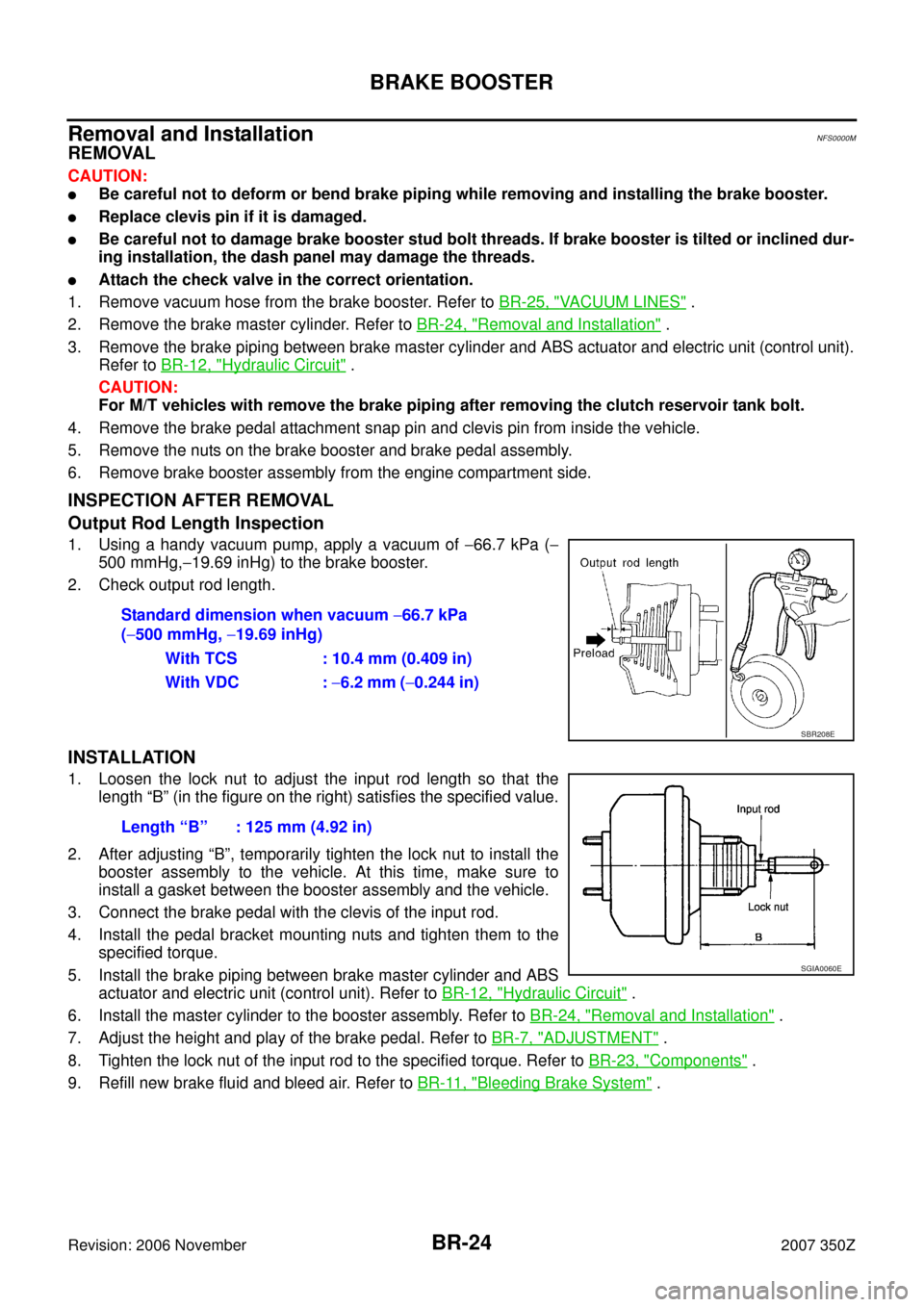
INSTALLATION
1. Loosen the lock nut to adjust the input rod length so that the
length “B” (in the figure on the right) satisfies the specified value.
2. After adjusting “B”, temporarily tighten the lock nut to install the
booster assembly to the vehicle. At this time, make sure to
install a gasket between the booster assembly and the vehicle.
3. Connect the brake pedal with the clevis of the input rod.
4. Install the pedal bracket mounting nuts and tighten them to the
specified torque.
5. Install the brake piping between brake master cylinder and ABS
actuator and electric unit (control unit). Refer to BR-12, "
Hydraulic Circuit" .
6. Install the master cylinder to the booster assembly. Refer to BR-24, "
Removal and Installation" .
7. Adjust the height and play of the brake pedal. Refer to BR-7, "
ADJUSTMENT" .
8. Tighten the lock nut of the input rod to the specified torque. Refer to BR-23, "
Components" .
9. Refill new brake fluid and bleed air. Refer to BR-11, "
Bleeding Brake System" . Standard dimension when vacuum −66.7 kPa
(−500 mmHg, −19.69 inHg)
With TCS : 10.4 mm (0.409 in)
With VDC : −6.2 mm (−0.244 in)
SBR208E
Length “B” : 125 mm (4.92 in)
SGIA0060E