VACUUM LINES
BR-25
C
D
E
G
H
I
J
K
L
MA
B
BR
Revision: 2006 November2007 350Z
VACUUM LINESPFP:41920
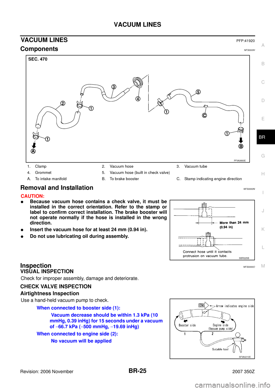
ComponentsNFS000IH
Removal and InstallationNFS0000N
CAUTION:
�Because vacuum hose contains a check valve, it must be
installed in the correct orientation. Refer to the stamp or
label to confirm correct installation. The brake booster will
not operate normally if the hose is installed in the wrong
direction.
�Insert the vacuum hose for at least 24 mm (0.94 in).
�Do not use lubricating oil during assembly.
InspectionNFS0000O
VISUAL INSPECTION
Check for improper assembly, damage and deteriorate.
CHECK VALVE INSPECTION
Airtightness Inspection
Use a hand-held vacuum pump to check.
1. Clamp 2. Vacuum hose 3. Vacuum tube
4. Grommet 5. Vacuum hose (built in check valve)
A. To intake manifold B. To brake booster C. Stamp indicating engine direction
PFIA0893E
SBR225B
When connected to booster side (1):
Vacuum decrease should be within 1.3 kPa (10
mmHg, 0.39 inHg) for 15 seconds under a vacuum
of −66.7 kPa (−500 mmHg, −19.69 inHg)
When connected to engine side (2):
No vacuum will be applied
SFIA0210E