VACUUM LINES
BR-25
C
D
E
G
H
I
J
K
L
MA
B
BR
Revision: 2006 November2007 350Z
VACUUM LINESPFP:41920
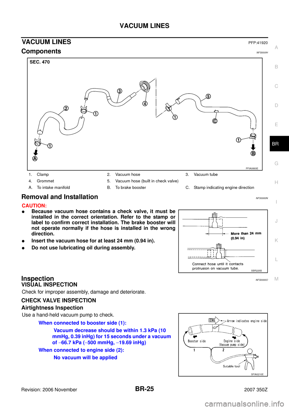
ComponentsNFS000IH
Removal and InstallationNFS0000N
CAUTION:
�Because vacuum hose contains a check valve, it must be
installed in the correct orientation. Refer to the stamp or
label to confirm correct installation. The brake booster will
not operate normally if the hose is installed in the wrong
direction.
�Insert the vacuum hose for at least 24 mm (0.94 in).
�Do not use lubricating oil during assembly.
InspectionNFS0000O
VISUAL INSPECTION
Check for improper assembly, damage and deteriorate.
CHECK VALVE INSPECTION
Airtightness Inspection
Use a hand-held vacuum pump to check.
1. Clamp 2. Vacuum hose 3. Vacuum tube
4. Grommet 5. Vacuum hose (built in check valve)
A. To intake manifold B. To brake booster C. Stamp indicating engine direction
PFIA0893E
SBR225B
When connected to booster side (1):
Vacuum decrease should be within 1.3 kPa (10
mmHg, 0.39 inHg) for 15 seconds under a vacuum
of −66.7 kPa (−500 mmHg, −19.69 inHg)
When connected to engine side (2):
No vacuum will be applied
SFIA0210E
FRONT DISC BRAKE
BR-29
C
D
E
G
H
I
J
K
L
MA
B
BR
Revision: 2006 November2007 350Z
�Burnish the brake pads and disc rotor mutually contacting surfaces after refinishing or replacing
rotors, after replacing pads, or if a soft pedal occurs at very low mileage. Refer to BR-38, "
Brake
Burnishing Procedure" .
Removal and Installation of Brake Pad (Other than Brembo Calipers)NFS000AU
REMOVAL
1. Remove tires from vehicle with a power tool.
2. Remove lower sliding pin bolt.
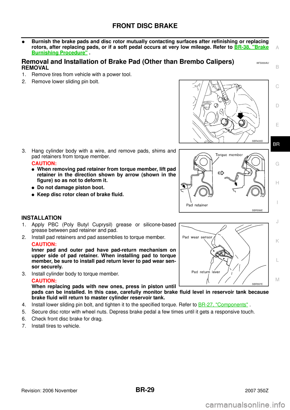
3. Hang cylinder body with a wire, and remove pads, shims and
pad retainers from torque member.
CAUTION:
�When removing pad retainer from torque member, lift pad
retainer in the direction shown by arrow (shown in the
figure) so as not to deform it.
�Do not damage piston boot.
�Keep disc rotor clean of brake fluid.
INSTALLATION
1. Apply PBC (Poly Butyl Cuprysil) grease or silicone-based
grease between pad retainer and pad.
2. Install pad retainers and pad assemblies to torque member.
CAUTION:
Inner pad and outer pad have pad-return mechanism on
upper side of pad retainer. When installing pad to torque
member, be sure to install pad return lever to pad wear sen-
sor securely.
3. Install cylinder body to torque member.
CAUTION:
When replacing pads with new ones, press in piston until
pads can be installed. In this case, carefully monitor brake fluid level in reservoir tank because
brake fluid will return to master cylinder reservoir tank.
4. Install lower sliding pin bolt, and tighten it to the specified torque. Refer to BR-27, "
Components" .
5. Secure disc rotor with wheel nuts. Depress brake pedal a few times until it gets a responsive touch.
6. Check front disc brake for drag.
7. Install tires to vehicle.
SBR433D
SBR556E
SBR557E