2007 NISSAN 350Z timing belt
[x] Cancel search: timing beltPage 1 of 134

BRC-1
BRAKE CONTROL SYSTEM
F BRAKES
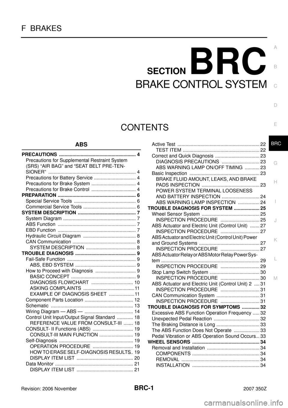
CONTENTS
C
D
E
G
H
I
J
K
L
M
SECTION BRC
A
B
BRC
Revision: 2006 November2007 350Z
BRAKE CONTROL SYSTEM
ABS
PRECAUTIONS .......................................................... 4
Precautions for Supplemental Restraint System
(SRS) “AIR BAG” and “SEAT BELT PRE-TEN-
SIONER” .................................................................. 4
Precautions for Battery Service ................................ 4
Precautions for Brake System .................................. 4
Precautions for Brake Control .................................. 4
PREPARATION ........................................................... 6
Special Service Tools ............................................... 6
Commercial Service Tools ........................................ 6
SYSTEM DESCRIPTION ............................................ 7
System Diagram ....................................................... 7
ABS Function ........................................................... 7
EBD Function ........................................................... 7
Hydraulic Circuit Diagram ........................................ 8
CAN Communication ................................................ 8
SYSTEM DESCRIPTION ...................................... 8
TROUBLE DIAGNOSIS .............................................. 9
Fail-Safe Function .................................................... 9
ABS, EBD SYSTEM .............................................. 9
How to Proceed with Diagnosis ............................... 9
BASIC CONCEPT ................................................. 9
DIAGNOSIS FLOWCHART ................................ 10
ASKING COMPLAINTS ....................................... 11
EXAMPLE OF DIAGNOSIS SHEET .................... 11
Component Parts Location ..................................... 12
Schematic .............................................................. 13
Wiring Diagram — ABS — ..................................... 14
Control Unit Input/Output Signal Standard ............. 18
REFERENCE VALUE FROM CONSULT-III ........ 18
CONSULT- II Functions (ABS) ............................... 19
CONSULT-III MAIN FUNCTION .......................... 19
Self-Diagnosis ........................................................ 19
OPERATION PROCEDURE ............................... 19
HOW TO ERASE SELF-DIAGNOSIS RESULTS ... 19
DISPLAY ITEM LIST ........................................... 20
Data Monitor ........................................................... 21
DISPLAY ITEM LIST ........................................... 21Active Test .............................................................. 22
TEST ITEM .......................................................... 22
Correct and Quick Diagnosis .................................. 23
DIAGNOSIS PRECAUTIONS ............................. 23
ABS WARNING LAMP ON/OFF TIMING ............ 23
Basic Inspection ..................................................... 23
BRAKE FLUID AMOUNT, LEAKS, AND BRAKE
PADS INSPECTION ............................................ 23
POWER SYSTEM TERMINAL LOOSENESS
AND BATTERY INSPECTION ............................. 24
ABS WARNING LAMP INSPECTION ................. 24
TROUBLE DIAGNOSIS FOR SYSTEM .................... 25
Wheel Sensor System ............................................ 25
INSPECTION PROCEDURE .............................. 25
ABS Actuator and Electric Unit (Control Unit) ........ 27
INSPECTION PROCEDURE .............................. 27
ABS Actuator and Electric Unit (Control Unit) Power
and Ground Systems .............................................. 27
INSPECTION PROCEDURE .............................. 27
ABS Actuator Relay or ABS Motor Relay Power Sys-
tem .......................................................................... 29
INSPECTION PROCEDURE .............................. 29
Stop Lamp Switch System ...................................... 30
INSPECTION PROCEDURE .............................. 30
ABS Actuator and Electric Unit (Control Unit) 2 ..... 31
INSPECTION PROCEDURE .............................. 31
CAN Communication System ................................. 31
INSPECTION PROCEDURE .............................. 31
TROUBLE DIAGNOSIS FOR SYMPTOMS .............. 32
Excessive ABS Function Operation Frequency ...... 32
Unexpected Pedal Reaction ................................... 32
The Braking Distance is Long ................................. 33
The ABS Function Does Not Operate .................... 33
Pedal Vibration or ABS Operation Sound Occurs ... 33
WHEEL SENSORS ................................................... 34
Removal and Installation ........................................ 34
COMPONENTS ................................................... 34
REMOVAL ........................................................... 34
INSTALLATION ................................................... 34
Page 2 of 134

BRC-2Revision: 2006 November2007 350Z SENSOR ROTOR ...................................................... 35
Removal and Installation ........................................ 35
REMOVAL ........................................................... 35
INSTALLATION .................................................... 35
ABS ACTUATOR AND ELECTRIC UNIT (ASSEM-
BLY) ........................................................................... 36
Removal and Installation ........................................ 36
COMPONENTS ................................................... 36
TCS/ABS
PRECAUTIONS ......................................................... 37
Precautions for Supplemental Restraint System
(SRS) “AIR BAG” and “SEAT BELT PRE-TEN-
SIONER” ................................................................. 37
Precautions for Battery Service .............................. 37
Precautions for Brake System ................................ 37
Precautions for Brake Control ................................ 37
PREPARATION ......................................................... 39
Special Service Tools ............................................. 39
Commercial Service Tools ...................................... 39
SYSTEM DESCRIPTION .......................................... 40
System Diagram ..................................................... 40
TCS Function .......................................................... 40
ABS Function .......................................................... 40
EBD Function ......................................................... 40
Hydraulic Circuit Diagram ....................................... 41
CAN Communication .............................................. 41
SYSTEM DESCRIPTION .................................... 41
TROUBLE DIAGNOSIS ............................................ 42
Fail-Safe Function .................................................. 42
TCS SYSTEM ...................................................... 42
ABS, EBD SYSTEM ............................................ 42
How to Proceed with Diagnosis .............................. 42
BASIC CONCEPT ............................................... 42
DIAGNOSIS FLOWCHART ................................. 43
ASKING COMPLAINTS ....................................... 44
EXAMPLE OF DIAGNOSIS SHEET .................... 44
Component Parts Location ..................................... 45
Schematic ............................................................... 46
Wiring Diagram — TCS — ..................................... 47
Control Unit Input/Output Signal Standard .............. 51
REFERENCE VALUE FROM CONSULT-III ........ 51
CONSULT- II Functions (ABS) ................................ 52
CONSULT-III MAIN FUNCTION .......................... 52
Self-diagnosis ......................................................... 53
OPERATION PROCEDURE ................................ 53
HOW TO ERASE SELF-DIAGNOSIS RESULTS ... 53
DISPLAY ITEM LIST ........................................... 53
Data Monitor ........................................................... 55
DISPLAY ITEM LIST ........................................... 55
Active Test .............................................................. 57
TEST ITEM .......................................................... 57
Correct and Quick Diagnosis .................................. 57
DIAGNOSIS PRECAUTIONS .............................. 57
ABS WARNING LAMP, TCS OFF INDICATOR
LAMP AND SLIP INDICATOR LAMP ON/OFF TIMING ................................................................ 59
Basic Inspection ...................................................... 59
BRAKE FLUID AMOUNT, LEAKS, AND BRAKE
PADS INSPECTION ............................................ 59
POWER SYSTEM TERMINAL LOOSENESS
AND BATTERY INSPECTION ............................. 59
ABS WARNING LAMP, TCS OFF INDICATOR
LAMP, SLIP INDICATOR LAMP INSPECTION .... 60
TROUBLE DIAGNOSIS FOR SYSTEM .................... 61
Wheel Sensor System ............................................ 61
INSPECTION PROCEDURE ............................... 61
Engine System ........................................................ 63
INSPECTION PROCEDURE ............................... 63
ABS Actuator and Electric Unit (Control Unit) ......... 63
INSPECTION PROCEDURE ............................... 63
ABS Actuator and Electric Unit (Control Unit) Power
and Ground Systems .............................................. 64
INSPECTION PROCEDURE ............................... 64
ABS Actuator Relay or ABS Motor Relay Power Sys-
tem .......................................................................... 65
INSPECTION PROCEDURE ............................... 65
Stop Lamp Switch System ...................................... 66
INSPECTION PROCEDURE ............................... 66
ABS Actuator and Electric Unit (Control Unit) 2 ...... 67
INSPECTION PROCEDURE ............................... 67
CAN Communication System ................................. 67
INSPECTION PROCEDURE ............................... 67
Component Inspection ............................................ 68
TCS OFF SWITCH .............................................. 68
TROUBLE DIAGNOSIS FOR SYMPTOMS .............. 69
Excessive ABS Function Operation Frequency ...... 69
Unexpected Pedal Reaction ................................... 70
The Braking Distance Is Long ................................. 70
The ABS Function Does Not Operate ..................... 70
Pedal Vibration or ABS Operation Sound Occurs ... 71
The Vehicle Jerks Around During TCS/ABS Control ... 71
WHEEL SENSORS ................................................... 73
Removal and Installation ......................................... 73
COMPONENTS ................................................... 73
REMOVAL ............................................................ 73
INSTALLATION .................................................... 73
SENSOR ROTOR ...................................................... 74
Removal and Installation ......................................... 74
REMOVAL ............................................................ 74
INSTALLATION .................................................... 74
ABS ACTUATOR AND ELECTRIC UNIT (ASSEM-
BLY) ........................................................................... 75
Removal and Installation ......................................... 75
COMPONENTS ................................................... 75
VDC/TCS/ABS
PRECAUTIONS ......................................................... 76
Precautions for Supplemental Restraint System
(SRS) “AIR BAG” and “SEAT BELT PRE-TEN-
SIONER” ................................................................. 76
Precautions for Battery Service .............................. 76
Precautions for Brake System ................................ 76
Precautions for Brake Control ................................. 77