Page 305 of 312

ASSEMBLY
AT-305
D
E
F
G
H
I
J
K
L
MA
B
AT
Revision: 2006 November2007 350Z
3. Install oil pump assembly in transmission case.
CAUTION:
Apply ATF to oil pump bearing.
4. Apply recommended sealant (Genuine RTV Silicone Sealant or
equivalent. Refer to GI-45, "
Recommended Chemical Products
and Sealants" .) to oil pump assembly as shown in the figure.
CAUTION:
Completely remove all moisture, oil and old sealant, etc.
from the oil pump mounting bolts and oil pump mounting
bolt mounting surfaces.
5. Tighten oil pump mounting bolts to the specified torque. Refer to
AT- 2 4 6 , "
Components" .
CAUTION:
Apply ATF to oil pump bushing.
6. Install O-ring to input clutch assembly.
CAUTION:
�Do not reuse O-ring.
�Apply ATF to O-ring.
7. Install converter housing to transmission case, and then tighten
converter housing bolts (A) and self-sealing bolts (B) to the
specified torque. Refer to AT- 2 4 6 , "
Components" .
CAUTION:
Do not reuse self-sealing bolts (B).
SCIA2811E
SCIA5321E
SCIA2300E
SCIA5011E
SCIA8085E
Page 307 of 312
ASSEMBLY
AT-307
D
E
F
G
H
I
J
K
L
MA
B
AT
Revision: 2006 November2007 350Z
e. Install A/T fluid temperature sensor 2 to bracket.
f. Install A/T fluid temperature sensor 2 (with bracket) in control
valve with TCM, and then tighten mounting bolt to the specified
torque. Refer to AT- 2 4 6 , "
Components" .
CAUTION:
Adjust bolt hole of bracket to bolt hole of control valve with
TCM.
g. Install control valve with TCM in transmission case.
CAUTION:
�Make sure that turbine revolution sensor securely installs
turbine revolution sensor hole.
�Hang down revolution sensor harness toward outside so
as not to disturb installation of control valve with TCM.
�Adjust A/T assembly harness connector of control valve
with TCM to terminal hole of transmission case.
�Assemble it so that manual valve cutout is engaged with
manual plate projection.
SCIA5264E
SCIA5301E
SCIA5034E
SCIA5035E
Page 308 of 312
AT-308
ASSEMBLY
Revision: 2006 November2007 350Z
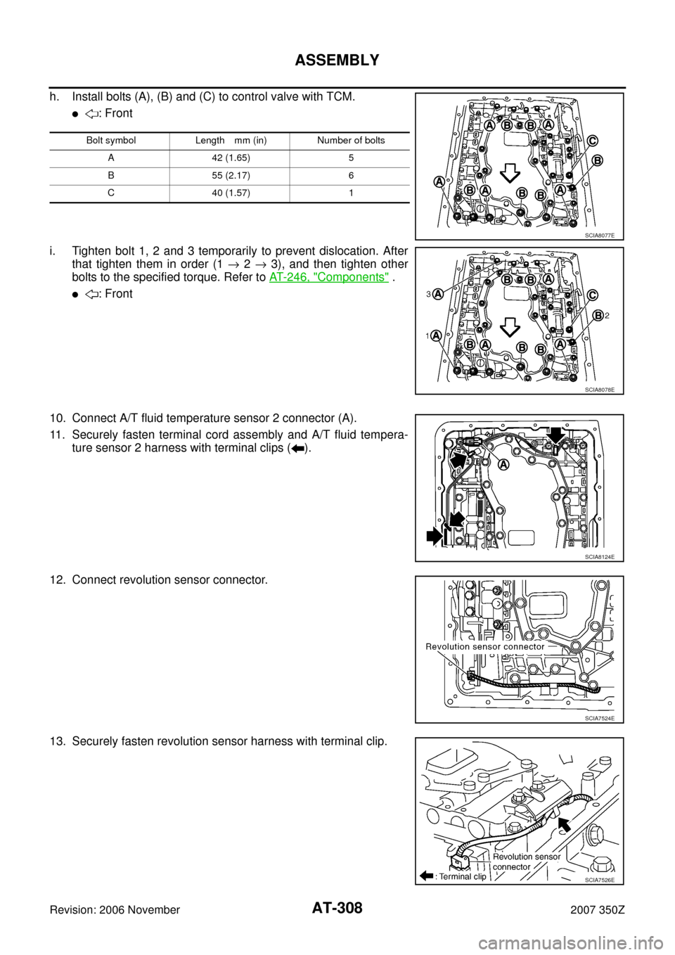
h. Install bolts (A), (B) and (C) to control valve with TCM.
�: Front
i. Tighten bolt 1, 2 and 3 temporarily to prevent dislocation. After
that tighten them in order (1 → 2 → 3), and then tighten other
bolts to the specified torque. Refer to AT- 2 4 6 , "
Components" .
�: Front
10. Connect A/T fluid temperature sensor 2 connector (A).
11. Securely fasten terminal cord assembly and A/T fluid tempera-
ture sensor 2 harness with terminal clips ( ).
12. Connect revolution sensor connector.
13. Securely fasten revolution sensor harness with terminal clip.
Bolt symbol Length mm (in) Number of bolts
A 42 (1.65) 5
B 55 (2.17) 6
C 40 (1.57) 1
SCIA8077E
SCIA8078E
SCIA8124E
SCIA7524E
SCIA7526E
Page 310 of 312
AT-310
ASSEMBLY
Revision: 2006 November2007 350Z
c. Tighten oil pan mounting bolts to the specified torque in numeri-
cal order shown in the figure after temporarily tightening them.
Refer to AT- 2 4 6 , "
Components" .
CAUTION:
Do not reuse oil pan mounting bolts.
18. Install drain plug to oil pan, and then tighten drain plug to the
specified torque. Refer to AT- 2 4 6 , "
Components" .
CAUTION:
Do not reuse drain plug gasket.
19. Install torque converter.
a. Pour ATF into torque converter.
�Approximately 2 liter (2-1/8 US qt, 1-3/4 Imp qt) of ATF is
required for a new torque converter.
�When reusing old torque converter, add the same amount
of ATF as was drained.
b. Install torque converter while aligning notches of torque con-
verter with notches of oil pump.
CAUTION:
Install torque converter while rotating it.
c. Measure distance “A” to check that torque converter is in proper
position.
SCIA4113E
SAT428DA
SCIA5010E
Distance “A”: 25.0 mm (0.98 in) or more
SCIA5694E
Page 311 of 312

AT-311
D
E
F
G
H
I
J
K
L
MA
B
AT
Revision: 2006 November2007 350Z
SERVICE DATA AND SPECIFICATIONS (SDS)PFP:00030
General SpecificationsNCS0009L
�*1: Refer to MA-1")
SERVICE DATA AND SPECIFICATIONS (SDS)
AT-311
D
E
F
G
H
I
J
K
L
MA
B
AT
Revision: 2006 November2007 350Z
SERVICE DATA AND SPECIFICATIONS (SDS)PFP:00030
General SpecificationsNCS0009L
�*1: Refer to MA-11, "Fluids and Lubricants" .
�*2: The fluid capacity is the reference value. Check the fluid level with A/T fluid level gauge.
Vehicle Speed at Which Gear Shifting OccursNCS0009M
�At half throttle, the accelerator opening is 4/8 of the full opening.
Vehicle Speed at Which Lock-up Occurs/ReleasesNCS0009N
�At closed throttle, the accelerator opening is less than 1/8 condition. (Closed throttle position signal: OFF)
�At half throttle, the accelerator opening is 4/8 of the full opening.
Stall SpeedNCS0009O
Line PressureNCS0009P
Applied modelVQ35HR engine
Automatic transmission model RE5R05A
Transmission model code number 98X5B
Stall torque ratio1.74 : 1
Transmission gear ratio1st 3.842
2nd 2.353
3rd 1.529
4th 1.000
5th 0.839
Reverse 2.765
Recommended fluid
Genuine NISSAN Matic J ATF
*1
Fluid capacity
10.3 liter (10-7/8 US qt, 9-1/8 Imp qt)*2
CAUTION:
�Use only Genuine NISSAN Matic J ATF. Do not mix with other fluid.
�Using A/T fluid other than Genuine NISSAN Matic J ATF will cause deterioration driveability and automatic transmission
durability, and may damage the automatic transmission, which is not covered by the NISSAN new vehicle limited warranty.
Throttle positionVehicle speed km/h (MPH)
D1 →D2D2 →D3D3 →D4D4 →D5D5 →D4D4 →D3D3 →D2D2 →D1
Full throttle 50 – 54
(31 – 34)97 – 105
(60 – 65)154 – 164
(96 – 102)224 – 234
(139 – 145)220 – 230
(137 – 143)145 – 155
(90 – 96)86 – 94
(53 – 58)39 – 43
(24 – 27)
Half throttle 29 – 33
(18 – 21)63 – 69
(39 – 43)100 – 108
(62 – 67)136 – 144
(85 – 89)88 – 96
(55 – 60)64 – 72
(40 – 45)28 – 34
(17 – 21)9 – 13
(6 – 8)
Throttle positionVehicle speed km/h (MPH)
Lock-up ON Lock-up OFF
Closed throttle 62 – 70 (39 – 44) 59 – 67 (37 – 42)
Half throttle 136 – 144 (85 – 89) 88 – 96 (55 – 60)
Stall speed2,700 – 3,000 rpm
Engine speedLine pressure kPa (kg/cm
2 , psi)
“R” position “D” and “M” positions
At idle speed 425 – 465 (4.3 – 4.7, 62 – 67) 379 – 428 (3.9 – 4.4, 55 – 62)
At stall speed 1,605 – 1,950 (16.4 – 19.9, 233 – 283) 1,310 – 1,500 (13.4 – 15.3, 190 – 218)
 in control
val")