Page 244 of 312
 with power tool. Refer to AT- 2 4 2 , \"Removal and Installation\" .
26. Remove bolts fixing A/")
AT-244
TRANSMISSION ASSEMBLY
Revision: 2006 November2007 350Z
25. Remove engine mounting insulator (rear) with power tool. Refer to AT- 2 4 2 , "Removal and Installation" .
26. Remove bolts fixing A/T assembly to engine assembly with power tool.
27. Remove A/T assembly from vehicle with a transmission jack.
�Secure torque converter to prevent it from dropping.
�Secure A/T assembly to a transmission jack.
28. Remove air breather hose. Refer to AT- 2 4 1 , "
Removal and
Installation" .
INSPECTION
Installation and Inspection of Torque Converter
�After inserting a torque converter to a A/T, be sure to check dis-
tance “A” to ensure it is within the reference value limit.
INSTALLATION
Install the removed parts in the reverse order of the removal, while paying attention to the following work.
�When installing A/T assembly to the engine assembly, attach the
fixing bolts in accordance with the following standard.
–: Engine to transmission
–: Transmission to engine
�Align the positions of tightening bolts for drive plate with those of
the torque converter, and temporarily tighten the bolts. Then
tighten the bolts with the specified torque.
CAUTION:
�When turning crankshaft, turn it clockwise as viewed from
the front of the engine.
�When tightening the tightening bolts for torque converter
after fixing crankshaft pulley bolts, be sure to confirm the
tightening torque of crankshaft pulley mounting bolts.
Refer to EM-53, "
TIMING CHAIN" .
�After converter is installed to drive plate, rotate crankshaft several turns and check to be sure that
transmission rotates freely without binding.
�Install crankshaft position sensor (POS). Refer to EM-26, "Removal and Installation" .
SCIA0499E
Distance “A”: 25.0 mm (0.98 in) or more
SCIA5694E
Bolt symbol A B
Number of bolts 8 4
Bolt length mm (in) 65 (2.56) 35 (1.38)
Tightening torque
N·m (kg-m, ft-lb)75 (7.7, 55) 46.6 (4.8, 34)
SCIA8152E
: 51 N·m (5.2 kg-m, 38 ft-lb)
SCIA1493E
Page 247 of 312

OVERHAUL
AT-247
D
E
F
G
H
I
J
K
L
MA
B
AT
Revision: 2006 November2007 350Z
1. O-ring 2. Oil pump cover 3. O-ring
4. Oil pump housing 5. Self-sealing bolt 6. Torque converter
7. Converter housing 8. Oil pump housing oil seal 9. Bearing race
10. Needle bearing 11. O-ring 12. Front carrier assembly
13. Needle bearing 14. Snap ring 15. Front sun gear
16. 3rd one-way clutch 17. Snap ring 18. Bearing race
19. Needle bearing 20. Seal ring 21. Input clutch assembly
22. Needle bearing 23. Rear internal gear 24. Brake band
25. Mid carrier assembly 26. Needle bearing 27. Bearing race
28. Rear carrier assembly 29. Needle bearing 30. Mid sun gear
31. Seal ring 32. Rear sun gear 33. 1st one-way clutch
34. Snap ring 35. Needle bearing 36. High and low reverse clutch hub
37. Snap ring 38. Bearing race 39. Needle bearing
Refer to GI section to make sure icons (symbol marks) in the figure. Refer to GI-11, "
Components" .
However, refer to the following for others.
: Apply Genuine RTV silicone sealant or equivalent. Refer to GI-45, "
Recommended Chemical Products and Sealants" .
Page 255 of 312
DISASSEMBLY
AT-255
D
E
F
G
H
I
J
K
L
MA
B
AT
Revision: 2006 November2007 350Z
DISASSEMBLYPFP:31020
DisassemblyNCS0009B
CAUTION:
Do not disassemble parts behind Drum Support. Refer to AT- 1 7 , "
Cross-sectional View" .
1. Drain ATF through drain hole.
2. Remove torque converter by holding it firmly and turing while
pulling straight out.
3. Check torque converter one-way clutch using check tool as
shown at figure.
a. Insert check tool into the groove of bearing support built into
one-way clutch outer race.
b. When fixing bearing support with check tool, rotate one- way
clutch spline using screwdriver.
c. Check that inner race rotates clockwise only. If not, replace
torque converter assembly.
4. Remove tightening bolts ( ) for converter housing and trans-
mission case.
5. Remove converter housing from transmission case.
CAUTION:
Be careful not to scratch converter housing.
SCIA5010E
SCIA3171E
SCIA8096E
Page 273 of 312
REPAIR FOR COMPONENT PARTS
AT-273
D
E
F
G
H
I
J
K
L
MA
B
AT
Revision: 2006 November2007 350Z
3. Install oil pump housing oil seal to the oil pump housing until it is
flush using the drift.
CAUTION:
�Do not reuse oil seal.
�Apply ATF to oil seal.
4. Install oil pump housing to oil pump cover.
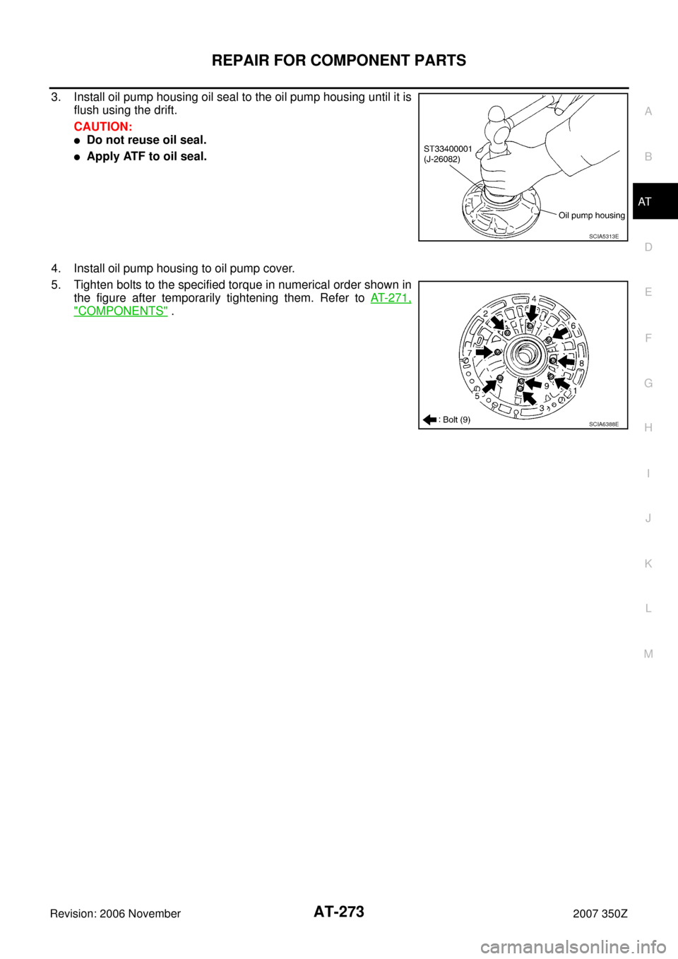
5. Tighten bolts to the specified torque in numerical order shown in
the figure after temporarily tightening them. Refer to AT- 2 7 1 ,
"COMPONENTS" .
SCIA5313E
SCIA6388E
Page 290 of 312
AT-290
ASSEMBLY
Revision: 2006 November2007 350Z
ASSEMBLYPFP:00000
Assembly (1)NCS0009I
1. As shown in the right figure, use a drift [commercial service tool:
22 mm (0.87 in) dia.] to drive manual shaft oil seals into trans-
mission case until it is flush.
CAUTION:
�Do not reuse manual shaft oil seals.
�Apply ATF to manual shaft oil seals.
2. Install detent spring and spacer to transmission case, and then
tighten mounting bolt to the specified torque. Refer to AT- 2 4 6 ,
"Components" .
3. Install manual shaft to transmission case.
4. Install parking rod to manual plate.
SCIA5259E
SCIA5248E
SCIA5716E
SCIA5220E
Page 295 of 312

ASSEMBLY
AT-295
D
E
F
G
H
I
J
K
L
MA
B
AT
Revision: 2006 November2007 350Z
22. Measure clearance between retaining plate and snap ring. If not
within specified clearance, select proper retaining plate. Refer to
“Parts Information” for retaining plate selection.
23. Install needle bearing to transmission case.
CAUTION:
�Take care with the direction of needle bearing. Refer to
AT- 2 5 3 , "
Locations of Adjusting Shims, Needle Bearings,
Thrust Washers and Snap Rings" .
�Apply petroleum jelly to needle bearing.
24. Install revolution sensor to transmission case, and then tighten
mounting bolt to the specified torque. Refer to AT- 2 4 6 , "
Compo-
nents" .
CAUTION:
�Do not subject it to impact by dropping or hitting it.
�Do not disassemble.
�Do not allow metal filings, etc. to get on the sensor's front
edge magnetic area.
�Do not place in an area affected by magnetism.
25. As shown in the figure, drive rear oil seal into rear extension until
it is flush using a drift.
CAUTION:
�Do not reuse rear oil seal.
�Apply ATF to rear oil seal.
26. Install return spring (1) to parking pawl (2).Specified clearance “A”:
Refer to AT- 3 1 2 , "
Reverse Brake" .
SCIA3129E
SCIA5031E
SCIA2320E
SCIA5311E
SCIA6180J
Page 297 of 312

ASSEMBLY
AT-297
D
E
F
G
H
I
J
K
L
MA
B
AT
Revision: 2006 November2007 350Z
32. Install output shaft in transmission case.
CAUTION:
Be careful not to mistake front for rear because both sides
looks similar. (Thinner end is front side.)
33. Install bearing race to output shaft.
34. Apply recommended sealant (Genuine Anaerobic Liquid Gasket
or equivalent. Refer to GI-45, "
Recommended Chemical Prod-
ucts and Sealants" .) to rear extension assembly as shown in
the figure.
CAUTION:
Completely remove all moisture, oil and old sealant, etc.
from transmission case and rear extension assembly
mounting surfaces.
35. Install rear extension assembly to transmission case.
CAUTION:
Insert the tip of parking rod between parking pawl and the
parking actuator support when assembling rear extension
assembly.
36. Tighten rear extension assembly mounting bolts to the specified
torque. Refer to AT- 2 4 6 , "
Components" .
CAUTION:
Do not reuse self-sealing bolts.
SCIA5030E
SCIA5245E
SCIA8228E
SCIA5029E
SCIA6941E
Page 302 of 312
AT-302
ASSEMBLY
Revision: 2006 November2007 350Z
55. Adjust brake band.
a. Loosen lock nut.
b. Tighten band servo anchor end pin to the specified torque.
c. Back of band servo anchor end pin three turns.
d. Holding band servo anchor end pin, tighten lock nut to the spec-
ified torque. Refer to AT- 2 4 6 , "
Components" .
AdjustmentNCS0009J
TOTAL END PLAY
�Measure clearance between front sun gear and bearing race for
oil pump cover.
�Select proper thickness of bearing race so that end play is within
specifications.
1. Measure dimensions “K” and “L” and then calculate dimension
“J”.
a. Measure dimension “K”.: 5.0 N·m (0.51 kg-m, 44 in-lb)
SCIA5498E
SCIA2810E
SCIA7073E
SCIA7074E

![NISSAN 350Z 2007 Z33 Automatic Transmission Workshop Manual AT-290
ASSEMBLY
Revision: 2006 November2007 350Z
ASSEMBLYPFP:00000
Assembly (1)NCS0009I
1. As shown in the right figure, use a drift [commercial service tool:
22 mm (0.87 in) dia.] to drive manual sha](/manual-img/5/755/w960_755-289.png "NISSAN 350Z 2007 Z33 Automatic Transmission Workshop Manual AT-290
ASSEMBLY
Revision: 2006 November2007 350Z
ASSEMBLYPFP:00000
Assembly (1)NCS0009I
1. As shown in the right figure, use a drift [commercial service tool:
22 mm (0.87 in) dia.] to drive manual sha")
