Page 241 of 312

AIR BREATHER HOSE
AT-241
D
E
F
G
H
I
J
K
L
MA
B
AT
Revision: 2006 November2007 350Z
AIR BREATHER HOSEPFP:31098
Removal and InstallationNCS00096
Refer to the figure below for air breather hose removal and installation procedure.
CAUTION:
�When installing an air breather hose, do not to crush or block by folding or bending the hose.
�When inserting air breather hose to air breather tube, be sure to insert it fully until its end reaches
the tube bend R portion.
�Install A/T air breather hose to air breather tube so that the paint mark is facing upward.
�Ensure clips are securely installed to brackets when installing A/T breather hose to brackets.
�When inserting air breather hose to air breather box, be sure to insert it fully until its end reaches
the stop.
�Install A/T air breather hose to air breather box so that the paint mark is facing backward.
�Install clip (1) at the paint mark (A).
–Air breather hose (2)
–Harness (3)
1. Air breather box 2. Air breather hose 3. Clip
4. Clip 5. A/T fluid charging pipe
A. Air breather tube
SCIA8151E
SCIA8268E
Page 243 of 312
.
�: Vehicle front
�: Bolt
6. Remove heated oxygen se")
TRANSMISSION ASSEMBLY
AT-243
D
E
F
G
H
I
J
K
L
MA
B
AT
Revision: 2006 November2007 350Z
5. Disconnect heated oxygen sensor 2 harness connectors (A).
�: Vehicle front
�: Bolt
6. Remove heated oxygen sensor 2 harness (B) from clips (1).
7. Remove bracket (2) from transmission assembly.
8. Remove front cross bar with power tool. Refer to FSU-8, "
Com-
ponents" .
9. Remove exhaust front tube and center muffler with power tool.
Refer to EX-3, "
Removal and Installation" .
10. Remove three way catalyst (right bank) and three way catalyst
(left bank). Refer to EM-22, "
Removal and Installation" .
11. Remove crankshaft position sensor (POS) (1). Refer to EM-26,
"Removal and Installation" .
�Three way catalyst (right bank) (2)
CAUTION:
�Do not subject it to impact by dropping or hitting it.
�Do not disassemble.
�Do not allow metal filings, etc. to get on the sensor's front
edge magnetic area.
�Do not place in an area affected by magnetism.
12. Remove rear propeller shaft. Refer to PR-6, "
Removal and
Installation" .
CAUTION:
Do not impact, or damage propeller shaft tube.
13. Remove control rod. Refer to AT- 2 0 5 , "
Control Rod Removal and Installation" .
14. Disconnect the following:
�A/T assembly harness connector
�S terminal connector (A)
�EPS solenoid valve harness connector (B)
15. Remove starter motor with power tool. Refer to SC-17,
"Removal and Installation" .
16. Remove A/T fluid level gauge.
17. Remove A/T fluid charging pipe
18. Remove O-ring from A/T fluid charging pipe.
19. Remove fluid cooler tube according to the following procedure.
a. Remove mounting nuts of the engine mounting insulator (LH) and engine mounting insulator (RH) on the
undersurface of the vehicle. Refer to EM-101, "
Removal and Installation" .
b. Push engine assembly upward from the vehicle with transmission jack to create clearance for removing
fluid cooler tube.
CAUTION:
Be careful with hoses and harness when pushing up the engine assembly.
c. Remove fluid cooler tube.
20. Plug up openings such as A/T fluid charging pipe hole, etc.
21. Remove rear plate cover from converter housing. Refer to EM-26, "
Removal and Installation" .
22. Turn crankshaft, and remove the four tightening bolts for drive plate and torque converter.
CAUTION:
When turning crankshaft, turn it clockwise as viewed from the front of the engine.
23. Support A/T assembly with a transmission jack.
CAUTION:
When setting the transmission jack, be careful not to allow it to collide against the drain plug.
24. Remove rear engine mounting member with power tool. Refer to AT- 2 4 2 , "
Removal and Installation" .
SCIA8269E
SCIA8272E
SCIA8273E
Page 244 of 312
 with power tool. Refer to AT- 2 4 2 , \"Removal and Installation\" .
26. Remove bolts fixing A/")
AT-244
TRANSMISSION ASSEMBLY
Revision: 2006 November2007 350Z
25. Remove engine mounting insulator (rear) with power tool. Refer to AT- 2 4 2 , "Removal and Installation" .
26. Remove bolts fixing A/T assembly to engine assembly with power tool.
27. Remove A/T assembly from vehicle with a transmission jack.
�Secure torque converter to prevent it from dropping.
�Secure A/T assembly to a transmission jack.
28. Remove air breather hose. Refer to AT- 2 4 1 , "
Removal and
Installation" .
INSPECTION
Installation and Inspection of Torque Converter
�After inserting a torque converter to a A/T, be sure to check dis-
tance “A” to ensure it is within the reference value limit.
INSTALLATION
Install the removed parts in the reverse order of the removal, while paying attention to the following work.
�When installing A/T assembly to the engine assembly, attach the
fixing bolts in accordance with the following standard.
–: Engine to transmission
–: Transmission to engine
�Align the positions of tightening bolts for drive plate with those of
the torque converter, and temporarily tighten the bolts. Then
tighten the bolts with the specified torque.
CAUTION:
�When turning crankshaft, turn it clockwise as viewed from
the front of the engine.
�When tightening the tightening bolts for torque converter
after fixing crankshaft pulley bolts, be sure to confirm the
tightening torque of crankshaft pulley mounting bolts.
Refer to EM-53, "
TIMING CHAIN" .
�After converter is installed to drive plate, rotate crankshaft several turns and check to be sure that
transmission rotates freely without binding.
�Install crankshaft position sensor (POS). Refer to EM-26, "Removal and Installation" .
SCIA0499E
Distance “A”: 25.0 mm (0.98 in) or more
SCIA5694E
Bolt symbol A B
Number of bolts 8 4
Bolt length mm (in) 65 (2.56) 35 (1.38)
Tightening torque
N·m (kg-m, ft-lb)75 (7.7, 55) 46.6 (4.8, 34)
SCIA8152E
: 51 N·m (5.2 kg-m, 38 ft-lb)
SCIA1493E
Page 255 of 312
DISASSEMBLY
AT-255
D
E
F
G
H
I
J
K
L
MA
B
AT
Revision: 2006 November2007 350Z
DISASSEMBLYPFP:31020
DisassemblyNCS0009B
CAUTION:
Do not disassemble parts behind Drum Support. Refer to AT- 1 7 , "
Cross-sectional View" .
1. Drain ATF through drain hole.
2. Remove torque converter by holding it firmly and turing while
pulling straight out.
3. Check torque converter one-way clutch using check tool as
shown at figure.
a. Insert check tool into the groove of bearing support built into
one-way clutch outer race.
b. When fixing bearing support with check tool, rotate one- way
clutch spline using screwdriver.
c. Check that inner race rotates clockwise only. If not, replace
torque converter assembly.
4. Remove tightening bolts ( ) for converter housing and trans-
mission case.
5. Remove converter housing from transmission case.
CAUTION:
Be careful not to scratch converter housing.
SCIA5010E
SCIA3171E
SCIA8096E
Page 258 of 312
AT-258
DISASSEMBLY
Revision: 2006 November2007 350Z
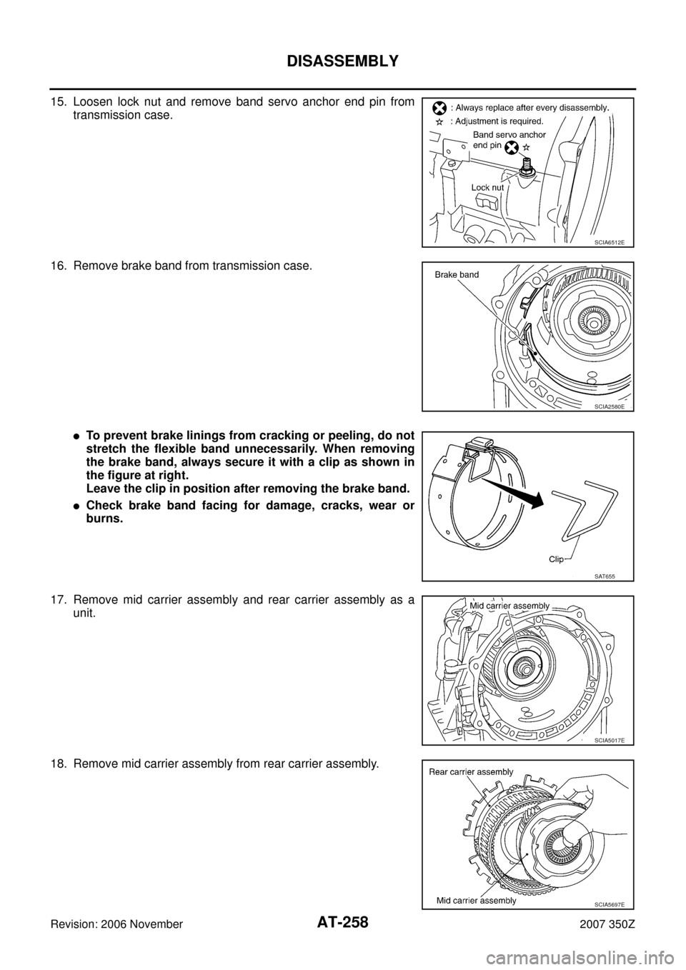
15. Loosen lock nut and remove band servo anchor end pin from
transmission case.
16. Remove brake band from transmission case.
�To prevent brake linings from cracking or peeling, do not
stretch the flexible band unnecessarily. When removing
the brake band, always secure it with a clip as shown in
the figure at right.
Leave the clip in position after removing the brake band.
�Check brake band facing for damage, cracks, wear or
burns.
17. Remove mid carrier assembly and rear carrier assembly as a
unit.
18. Remove mid carrier assembly from rear carrier assembly.
SCIA6512E
SCIA2580E
SAT655
SCIA5017E
SCIA5697E
Page 275 of 312
REPAIR FOR COMPONENT PARTS
AT-275
D
E
F
G
H
I
J
K
L
MA
B
AT
Revision: 2006 November2007 350Z
INSPECTION
3rd One-way Clutch
�Check frictional surface for wear or damage.
CAUTION:
If necessary, replace 3rd one-way clutch.
Front Sun Gear Snap Ring
�Check for deformation, fatigue or damage.
CAUTION:
If necessary, replace snap ring.
Front Sun Gear
�Check for deformation, fatigue or damage.
CAUTION:
If necessary, replace front sun gear.
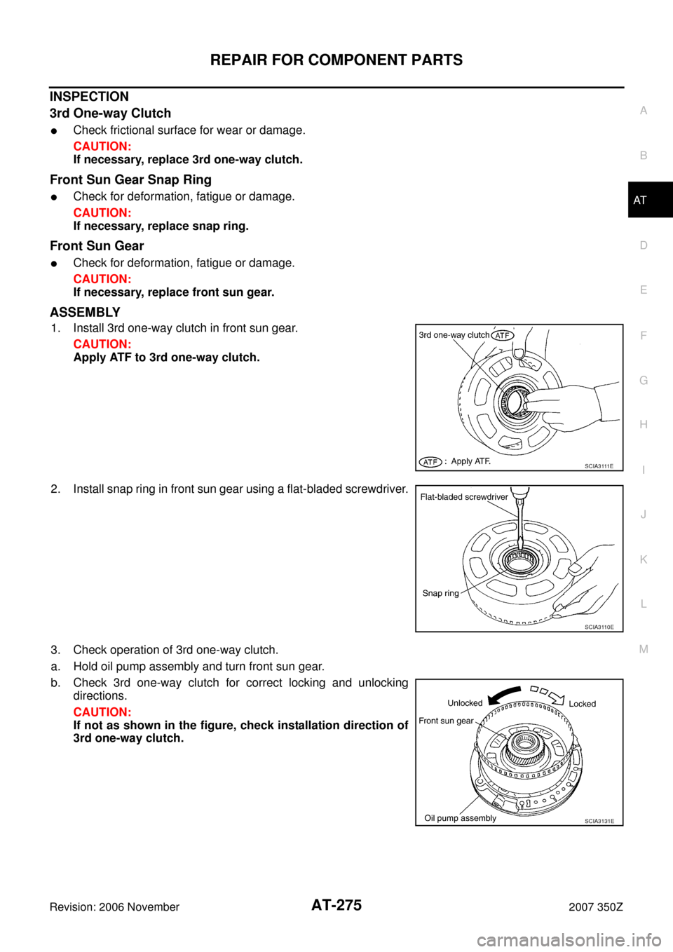
ASSEMBLY
1. Install 3rd one-way clutch in front sun gear.
CAUTION:
Apply ATF to 3rd one-way clutch.
2. Install snap ring in front sun gear using a flat-bladed screwdriver.
3. Check operation of 3rd one-way clutch.
a. Hold oil pump assembly and turn front sun gear.
b. Check 3rd one-way clutch for correct locking and unlocking
directions.
CAUTION:
If not as shown in the figure, check installation direction of
3rd one-way clutch.
S C I A 3 111 E
SCIA3110E
SCIA3131E
Page 285 of 312

REPAIR FOR COMPONENT PARTS
AT-285
D
E
F
G
H
I
J
K
L
MA
B
AT
Revision: 2006 November2007 350Z
5. Install needle bearing to high and low reverse clutch hub.
CAUTION:
�Take care with the direction of needle bearing. Refer to
AT- 2 5 3 , "
Locations of Adjusting Shims, Needle Bearings,
Thrust Washers and Snap Rings" .
�Apply petroleum jelly to needle bearing.
6. Install high and low reverse clutch hub to mid sun gear assem-
bly.
7. Install snap ring to mid sun gear assembly using pair of snap
ring pliers.
CAUTION:
Do not expand snap ring excessively.
8. Check operation of 1st one-way clutch.
a. Hold mid sun gear and turn rear sun gear.
b. Check 1st one-way clutch for correct locking and unlocking
directions.
CAUTION:
If not as shown in illustration, check installation direction of
1st one-way clutch.
9. Install bearing race and needle bearing to high and low reverse
clutch hub.
CAUTION:
�Take care with the direction of needle bearing. Refer to
AT- 2 5 3 , "
Locations of Adjusting Shims, Needle Bearings,
Thrust Washers and Snap Rings" .
�Apply petroleum jelly to needle bearing.
SCIA2857E
SCIA2856E
SCIA2855E
SCIA3132E
SCIA2854E
Page 301 of 312
ASSEMBLY
AT-301
D
E
F
G
H
I
J
K
L
MA
B
AT
Revision: 2006 November2007 350Z
50. Install band servo anchor end pin and lock nut in transmission
case.
CAUTION:
Do not reuse band servo anchor end pin.
51. Install brake band in transmission case.
CAUTION:
Assemble it so that identification to avoid incorrect installa-
tion faces servo side.
52. Install front sun gear to front carrier assembly.
CAUTION:
Apply ATF to front sun gear bearing and 3rd one-way clutch
end bearing.
53. Install needle bearing to front sun gear.
CAUTION:
�Take care with the direction of needle bearing. Refer to
AT- 2 5 3 , "
Locations of Adjusting Shims, Needle Bearings,
Thrust Washers and Snap Rings" .
�Apply petroleum jelly to needle bearing.
54. Adjust brake band tilting using a clip so that brake band contacts
front sun gear drum evenly.
SCIA6512E
SCIA5498E
SCIA5014E
SCIA2808E
SCIA5033E