Page 208 of 312
AT-208
A/T SHIFT LOCK SYSTEM
Revision: 2006 November2007 350Z
Wiring Diagram — AT — SHIFTNCS0008Y
TCWT0443E
Page 209 of 312

A/T SHIFT LOCK SYSTEM
AT-209
D
E
F
G
H
I
J
K
L
MA
B
AT
Revision: 2006 November2007 350Z
Diagnostic ProcedureNCS0008Z
SYMPTOM 1:
�Selector lever cannot be moved from “P” position with key in ON position and brake pedal
applied.
�Selector lever can be moved from “P” position with key in ON position and brake pedal released.
�Selector lever can be moved from “P” position when key is removed from key cylinder.
SYMPTOM 2:
�Ignition key cannot be removed when selector lever is set to “P” position.
�Ignition key can be removed when selector lever is set to any position except “P” position.
1. CHECK KEY INTERLOCK CABLE
Check the key interlock cable for damage.
OK or NG
OK >> GO TO 2.
NG >> Replace key interlock cable. Refer to AT- 2 1 2 , "
KEY INTERLOCK CABLE" .
2. CHECK SELECTOR LEVER POSITION
Check the selector lever position for damage. Refer to AT- 2 0 6 , "
Checking of A/T Position" .
OK or NG
OK >> GO TO 3.
NG >> Check selector lever. Refer to AT- 2 0 6 , "
Adjustment of A/T Position" .
3. CHECK POWER SOURCE
1. Turn ignition switch OFF.
2. Disconnect shift lock relay.
3. Check voltage between shift lock relay E19 terminal 2 and
ground.
OK or NG
OK >> GO TO 5.
NG >> GO TO 4.Vo l t a g e
Brake pedal depressed: Battery voltage
Brake pedal released: 0 V
SCIA6866E
Page 210 of 312

AT-210
A/T SHIFT LOCK SYSTEM
Revision: 2006 November2007 350Z
4. DETECT MALFUNCTIONING ITEM
Check the following.
�Harness for short or open between battery and stop lamp switch harness connector E111 terminal 3.
�Harness for short or open between stop lamp switch harness connector E111 terminal 4 and shift lock
relay E19 terminal 2.
�10 A fuse [No. 20, located in the fuse block (J/B)].
�Stop lamp switch.
–Check continuity between stop lamp switch harness connector E111 terminals 3 and 4.
Check stop lamp switch after adjusting brake pedal — refer to BR-7, "
BRAKE PEDAL".
OK or NG
OK >> GO TO 5.
NG >> Repair or replace damaged parts.
5. CHECK GROUND CIRCUIT
1. Turn ignition switch OFF.
2. Disconnect shift lock relay.
3. Check continuity between shift lock relay E19 terminal 1 and
ground.
CAUTION:
Connect test probe (BLACK) to shift lock relay, and test
probe (RED) to ground.
If OK, check harness for short to ground and short to power.
OK or NG
OK >> GO TO 6.
NG >> Repair open circuit or short to ground or short to power in harness or connectors.
6. CHECK INPUT SIGNAL A/T DEVICE
1. Turn ignition switch ON.
2. Selector lever is set in “P” position.
3. Check voltage between A/T device harness connector M47 ter-
minal 1 and ground.
OK or NG
OK >> GO TO 8.
NG >> GO TO 7.
SCIA3953E
Continuity should exist.
SCIA6931E
Vo l ta g e
Brake pedal depressed: Battery voltage
Brake pedal released: 0 V
SCIA7432E
Page 211 of 312

A/T SHIFT LOCK SYSTEM
AT-211
D
E
F
G
H
I
J
K
L
MA
B
AT
Revision: 2006 November2007 350Z
7. DETECT MALFUNCTIONING ITEM
Check the following.
�Harness for short or open between ignition switch and shift lock relay E19 terminal 5.
�Harness for short or open between shift lock relay E19 terminal 3 and A/T device harness connector M47
terminal 1.
�10 A fuse [No. 12, located in the fuse block (J/B)].
�Ignition switch (Refer to PG-4, "POWER SUPPLY ROUTING CIRCUIT" ).
�Shift lock relay.
–Check continuity between shift lock relay E19 terminal 3 and 5.
OK or NG
OK >> GO TO 8.
NG >> Repair or replace damaged parts.
8. CHECK GROUND CIRCUIT
1. Turn ignition switch OFF.
2. Disconnect A/T device harness connector.
3. Check continuity between A/T device harness connector M47
terminal 2 and ground.
If OK, check harness for short to ground and short to power.
OK or NG
OK >> GO TO 9.
NG >> Repair open circuit or short to ground or short to power
in harness or connectors.
9. CHECK SHIFT LOCK SOLENOID AND PARK POSITION SWITCH
1. Connect A/T device harness connector.
2. Turn ignition switch ON.
3. Selector lever is set in “P” position.
4. Check operation.
OK or NG
OK >>INSPECTION END.
NG >> Repair or replace damaged parts.
Condition Continuity
12V direct current supply between terminal 1 and 2 Yes
OFF No
SCIA1245E
Continuity should exist.
SCIA2125E
Condition Brake pedal Operation
When ignition switch is turned to “ON” position and selector lever is set in
“P” position.Depressed Yes
Released No
Page 212 of 312
AT-212
KEY INTERLOCK CABLE
Revision: 2006 November2007 350Z
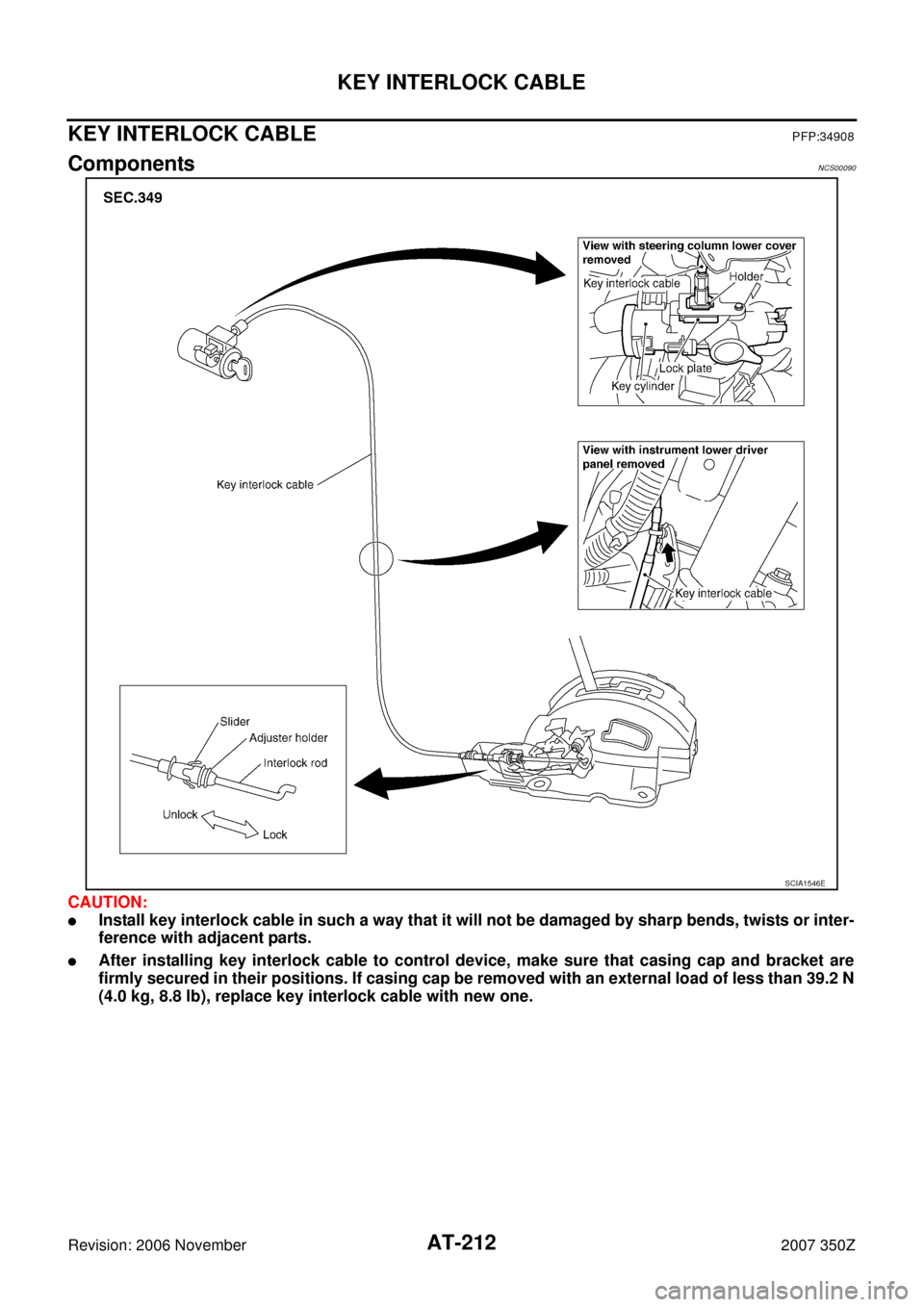
KEY INTERLOCK CABLEPFP:34908
ComponentsNCS00090
CAUTION:
�Install key interlock cable in such a way that it will not be damaged by sharp bends, twists or inter-
ference with adjacent parts.
�After installing key interlock cable to control device, make sure that casing cap and bracket are
firmly secured in their positions. If casing cap be removed with an external load of less than 39.2 N
(4.0 kg, 8.8 lb), replace key interlock cable with new one.
SCIA1546E
Page 213 of 312
KEY INTERLOCK CABLE
AT-213
D
E
F
G
H
I
J
K
L
MA
B
AT
Revision: 2006 November2007 350Z
Removal and InstallationNCS00091
REMOVAL
1. Unlock slider by squeezing lock tabs on slider from adjuster
holder.
2. Remove casing cap from bracket of control device assembly
and remove interlock rod from adjuster holder.
3. Remove lock plate from key cylinder.
4. Remove holder from key cylinder and remove key interlock
cable.
SCIA1230E
SCIA1549E
Page 214 of 312
AT-214
KEY INTERLOCK CABLE
Revision: 2006 November2007 350Z
INSTALLATION
1. Set holder of key interlock cable to key cylinder and install lock
plate.
CAUTION:
Do not reuse the lock plate
2. Clamp key interlock cable and fix to key interlock cable with
band.
3. Turn ignition key to lock position.
4. Set selector lever to “P” position.
5. Insert interlock rod into adjuster holder.
6. Install casing cap to bracket.
7. Move slider in order to fix adjuster holder to interlock rod.
CAUTION:
Do not touch any parts except slider. Do not add any force
to slider except force toward slider.
SCIA1549E
SCIA1232E
Page 236 of 312
.
�: Vehicle front
�: Bolt
8. Remove heated oxygen sensor 2 harness (B) from clips")
AT-236
ON-VEHICLE SERVICE
Revision: 2006 November2007 350Z
7. Disconnect heated oxygen sensor 2 harness connectors (A).
�: Vehicle front
�: Bolt
8. Remove heated oxygen sensor 2 harness (B) from clips (1).
9. Remove bracket (2) from transmission assembly.
10. Remove clip (1), oil pan (2) and oil pan gasket.
�: Vehicle front
�: Oil pan mounting bolt
�Drain plug (3)
11. Check foreign materials in oil pan to help determine causes of
malfunction. If the ATF is very dark, smells burned, or contains
foreign particles, the frictional material (clutches, band) may
need replacement. A tacky film that will not wipe clean indicates
varnish build up. Varnish can cause valves, servo, and clutches
to stick and can inhibit pump pressure.
�If frictional material is detected, perform A/T fluid cooler
cleaning. Refer to AT- 1 4 , "
A/T Fluid Cooler Cleaning".
12. Support transmission assembly with a transmission jack.
CAUTION:
When setting transmission jack, place wooden blocks to
prevent from damaging control valve with TCM and trans-
mission case.
13. Remove rear engine mounting member with power tool. Refer to AT- 2 4 2 , "
Removal and Installation" .
14. Remove tightening bolts for rear extension assembly and trans-
mission case.
SCIA8269E
SCIA8117E
SCIA5199E
SCIA6941E