Page 244 of 312
 with power tool. Refer to AT- 2 4 2 , \"Removal and Installation\" .
26. Remove bolts fixing A/")
AT-244
TRANSMISSION ASSEMBLY
Revision: 2006 November2007 350Z
25. Remove engine mounting insulator (rear) with power tool. Refer to AT- 2 4 2 , "Removal and Installation" .
26. Remove bolts fixing A/T assembly to engine assembly with power tool.
27. Remove A/T assembly from vehicle with a transmission jack.
�Secure torque converter to prevent it from dropping.
�Secure A/T assembly to a transmission jack.
28. Remove air breather hose. Refer to AT- 2 4 1 , "
Removal and
Installation" .
INSPECTION
Installation and Inspection of Torque Converter
�After inserting a torque converter to a A/T, be sure to check dis-
tance “A” to ensure it is within the reference value limit.
INSTALLATION
Install the removed parts in the reverse order of the removal, while paying attention to the following work.
�When installing A/T assembly to the engine assembly, attach the
fixing bolts in accordance with the following standard.
–: Engine to transmission
–: Transmission to engine
�Align the positions of tightening bolts for drive plate with those of
the torque converter, and temporarily tighten the bolts. Then
tighten the bolts with the specified torque.
CAUTION:
�When turning crankshaft, turn it clockwise as viewed from
the front of the engine.
�When tightening the tightening bolts for torque converter
after fixing crankshaft pulley bolts, be sure to confirm the
tightening torque of crankshaft pulley mounting bolts.
Refer to EM-53, "
TIMING CHAIN" .
�After converter is installed to drive plate, rotate crankshaft several turns and check to be sure that
transmission rotates freely without binding.
�Install crankshaft position sensor (POS). Refer to EM-26, "Removal and Installation" .
SCIA0499E
Distance “A”: 25.0 mm (0.98 in) or more
SCIA5694E
Bolt symbol A B
Number of bolts 8 4
Bolt length mm (in) 65 (2.56) 35 (1.38)
Tightening torque
N·m (kg-m, ft-lb)75 (7.7, 55) 46.6 (4.8, 34)
SCIA8152E
: 51 N·m (5.2 kg-m, 38 ft-lb)
SCIA1493E
Page 258 of 312
AT-258
DISASSEMBLY
Revision: 2006 November2007 350Z
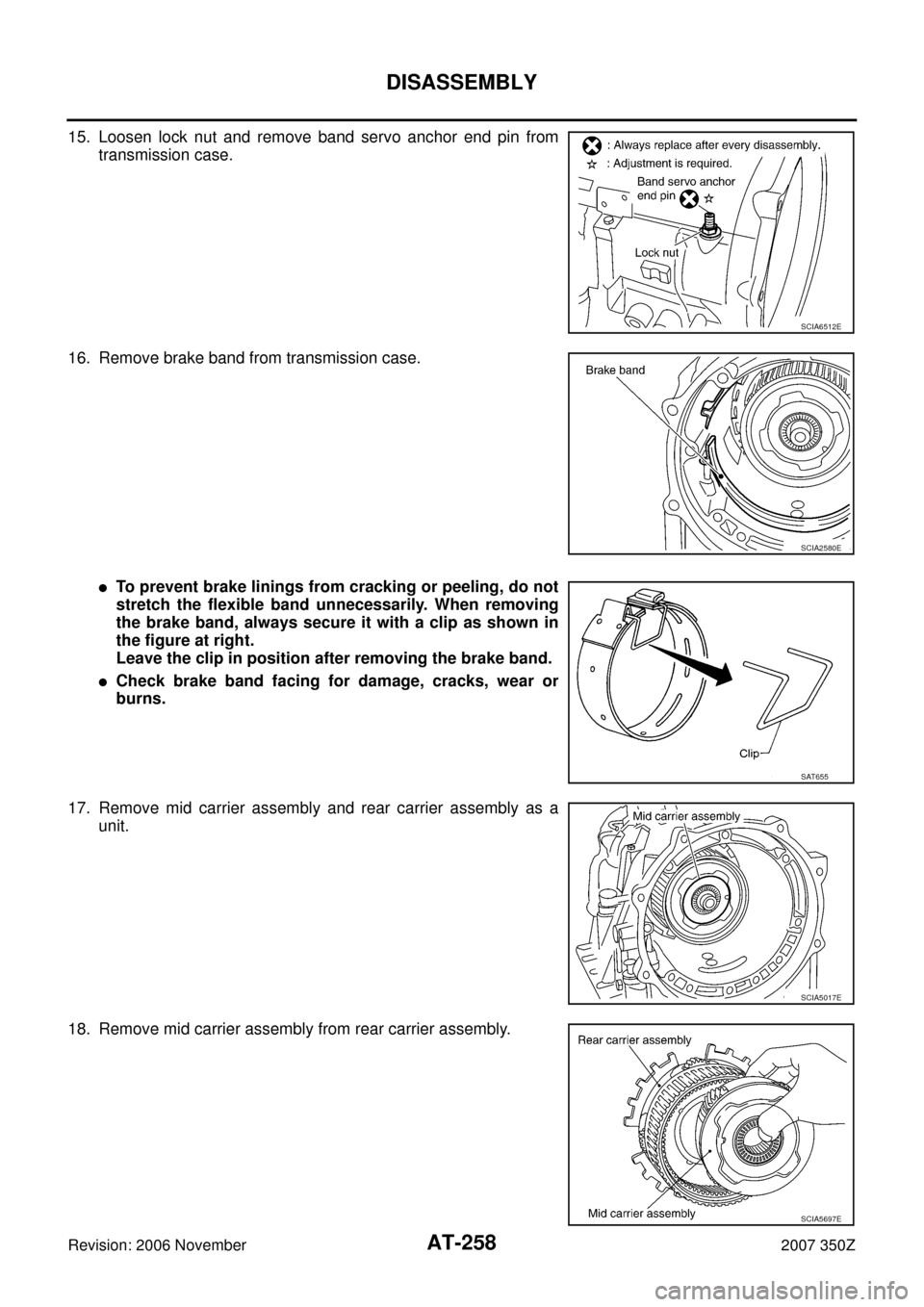
15. Loosen lock nut and remove band servo anchor end pin from
transmission case.
16. Remove brake band from transmission case.
�To prevent brake linings from cracking or peeling, do not
stretch the flexible band unnecessarily. When removing
the brake band, always secure it with a clip as shown in
the figure at right.
Leave the clip in position after removing the brake band.
�Check brake band facing for damage, cracks, wear or
burns.
17. Remove mid carrier assembly and rear carrier assembly as a
unit.
18. Remove mid carrier assembly from rear carrier assembly.
SCIA6512E
SCIA2580E
SAT655
SCIA5017E
SCIA5697E
Page 293 of 312
ASSEMBLY
AT-293
D
E
F
G
H
I
J
K
L
MA
B
AT
Revision: 2006 November2007 350Z
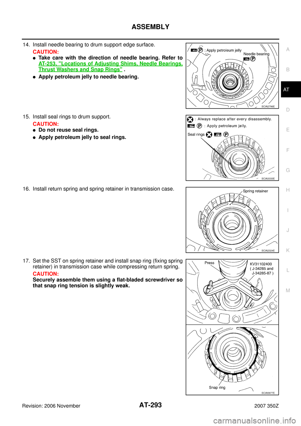
14. Install needle bearing to drum support edge surface.
CAUTION:
�Take care with the direction of needle bearing. Refer to
AT- 2 5 3 , "
Locations of Adjusting Shims, Needle Bearings,
Thrust Washers and Snap Rings" .
�Apply petroleum jelly to needle bearing.
15. Install seal rings to drum support.
CAUTION:
�Do not reuse seal rings.
�Apply petroleum jelly to seal rings.
16. Install return spring and spring retainer in transmission case.
17. Set the SST on spring retainer and install snap ring (fixing spring
retainer) in transmission case while compressing return spring.
CAUTION:
Securely assemble them using a flat-bladed screwdriver so
that snap ring tension is slightly weak.
SCIA2796E
SCIA3333E
SCIA2324E
SCIA5877E
Page 307 of 312
ASSEMBLY
AT-307
D
E
F
G
H
I
J
K
L
MA
B
AT
Revision: 2006 November2007 350Z
e. Install A/T fluid temperature sensor 2 to bracket.
f. Install A/T fluid temperature sensor 2 (with bracket) in control
valve with TCM, and then tighten mounting bolt to the specified
torque. Refer to AT- 2 4 6 , "
Components" .
CAUTION:
Adjust bolt hole of bracket to bolt hole of control valve with
TCM.
g. Install control valve with TCM in transmission case.
CAUTION:
�Make sure that turbine revolution sensor securely installs
turbine revolution sensor hole.
�Hang down revolution sensor harness toward outside so
as not to disturb installation of control valve with TCM.
�Adjust A/T assembly harness connector of control valve
with TCM to terminal hole of transmission case.
�Assemble it so that manual valve cutout is engaged with
manual plate projection.
SCIA5264E
SCIA5301E
SCIA5034E
SCIA5035E
Page 308 of 312
AT-308
ASSEMBLY
Revision: 2006 November2007 350Z
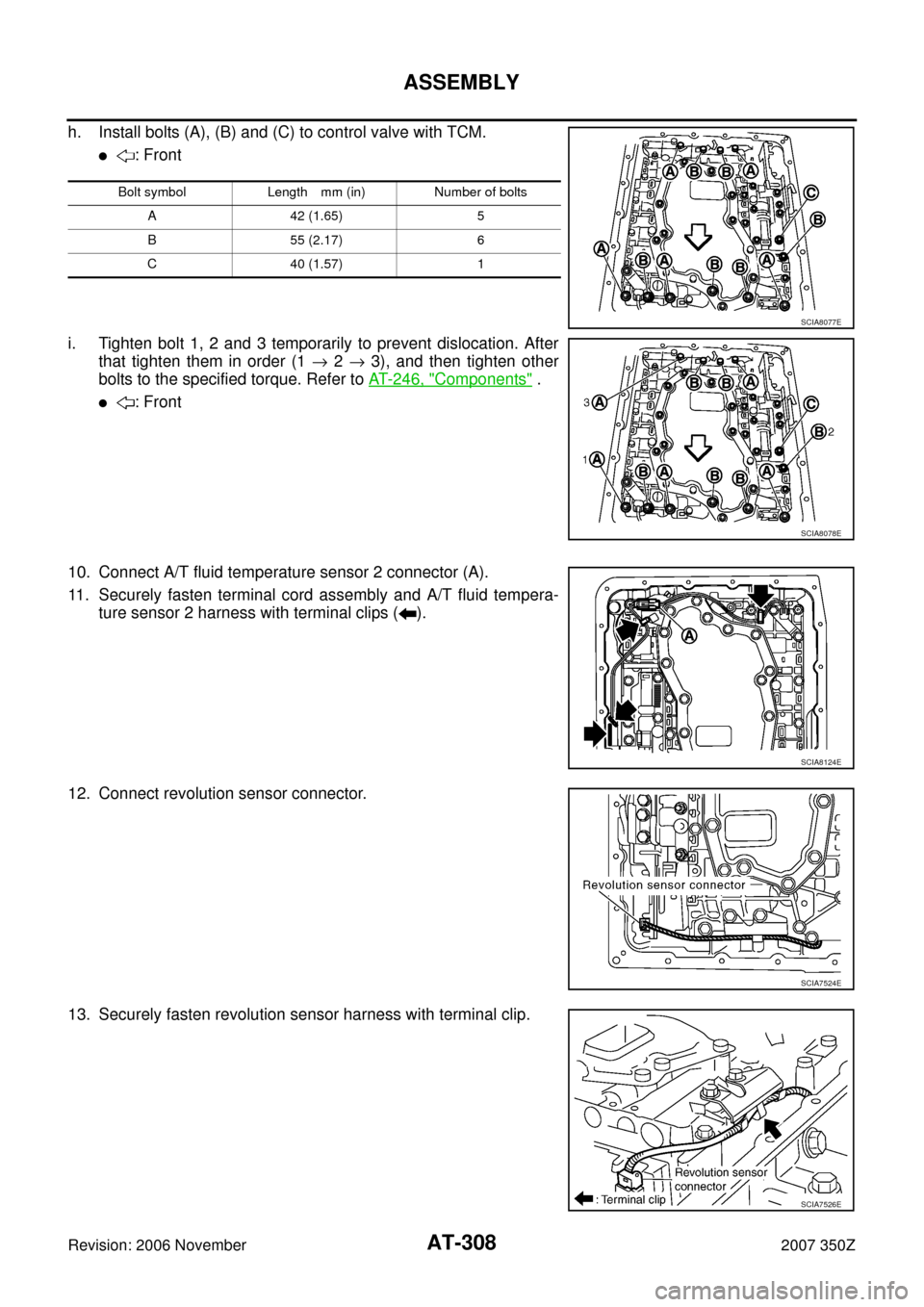
h. Install bolts (A), (B) and (C) to control valve with TCM.
�: Front
i. Tighten bolt 1, 2 and 3 temporarily to prevent dislocation. After
that tighten them in order (1 → 2 → 3), and then tighten other
bolts to the specified torque. Refer to AT- 2 4 6 , "
Components" .
�: Front
10. Connect A/T fluid temperature sensor 2 connector (A).
11. Securely fasten terminal cord assembly and A/T fluid tempera-
ture sensor 2 harness with terminal clips ( ).
12. Connect revolution sensor connector.
13. Securely fasten revolution sensor harness with terminal clip.
Bolt symbol Length mm (in) Number of bolts
A 42 (1.65) 5
B 55 (2.17) 6
C 40 (1.57) 1
SCIA8077E
SCIA8078E
SCIA8124E
SCIA7524E
SCIA7526E
 in control
val")