Page 167 of 312

BRAKE SIGNAL CIRCUIT
AT-167
D
E
F
G
H
I
J
K
L
MA
B
AT
Revision: 2006 November2007 350Z
BRAKE SIGNAL CIRCUITPFP:25320
CONSULT-III Reference ValueNCS00080
Diagnostic ProcedureNCS00081
1. CHECK CAN COMMUNICATION LINE
Perform self-diagnosis. Refer to AT- 8 6 , "
SELF-DIAGNOSTIC RESULT MODE" , AT- 9 2 , "TCM SELF-DIAG-
NOSTIC PROCEDURE (NO TOOLS)" .
Is a malfunction in the CAN communication indicated in the results?
YES >> Check CAN communication line. Refer to AT- 9 4 , "DTC U1000 CAN COMMUNICATION LINE" .
NO >> GO TO 2.
2. CHECK STOP LAMP SWITCH CIRCUIT
With CONSULT-III
1. Turn ignition switch ON.
2. Select “ECU INPUT SIGNALS” in “DATA MONITOR” mode for “TRANSMISSION” with CONSULT-III.
3. Read out ON/OFF switching action of the “BRAKE SW”.
OK or NG
OK >>INSPECTION END
NG >> GO TO 3.
3. CHECK STOP LAMP SWITCH
Check continuity between stop lamp switch harness connector E111
terminals 3 and 4. Refer to AT- 1 6 9 , "
Wiring Diagram — AT — NON-
DTC" .
Check stop lamp switch after adjusting brake pedal — refer to
BR-7, "
BRAKE PEDAL" .
OK or NG
OK >> Check the following. If NG, repair or replace damaged
parts.
�Harness for short or open between battery and stop lamp switch.
�Harness for short or open between stop lamp switch and unified meter and A/C amp.
�10 A fuse (No. 20, located in fuse block).
NG >> Repair or replace the stop lamp switch.
Item name Condition Display value
BRAKE SWDepressed brake pedal. ON
Released brake pedal. OFF
Item name Condition Display value
BRAKE SWDepressed brake pedal. ON
Released brake pedal. OFF
Condition Continuity
When brake pedal is depressed Yes
When brake pedal is released No
SCIA2126E
Page 212 of 312
AT-212
KEY INTERLOCK CABLE
Revision: 2006 November2007 350Z
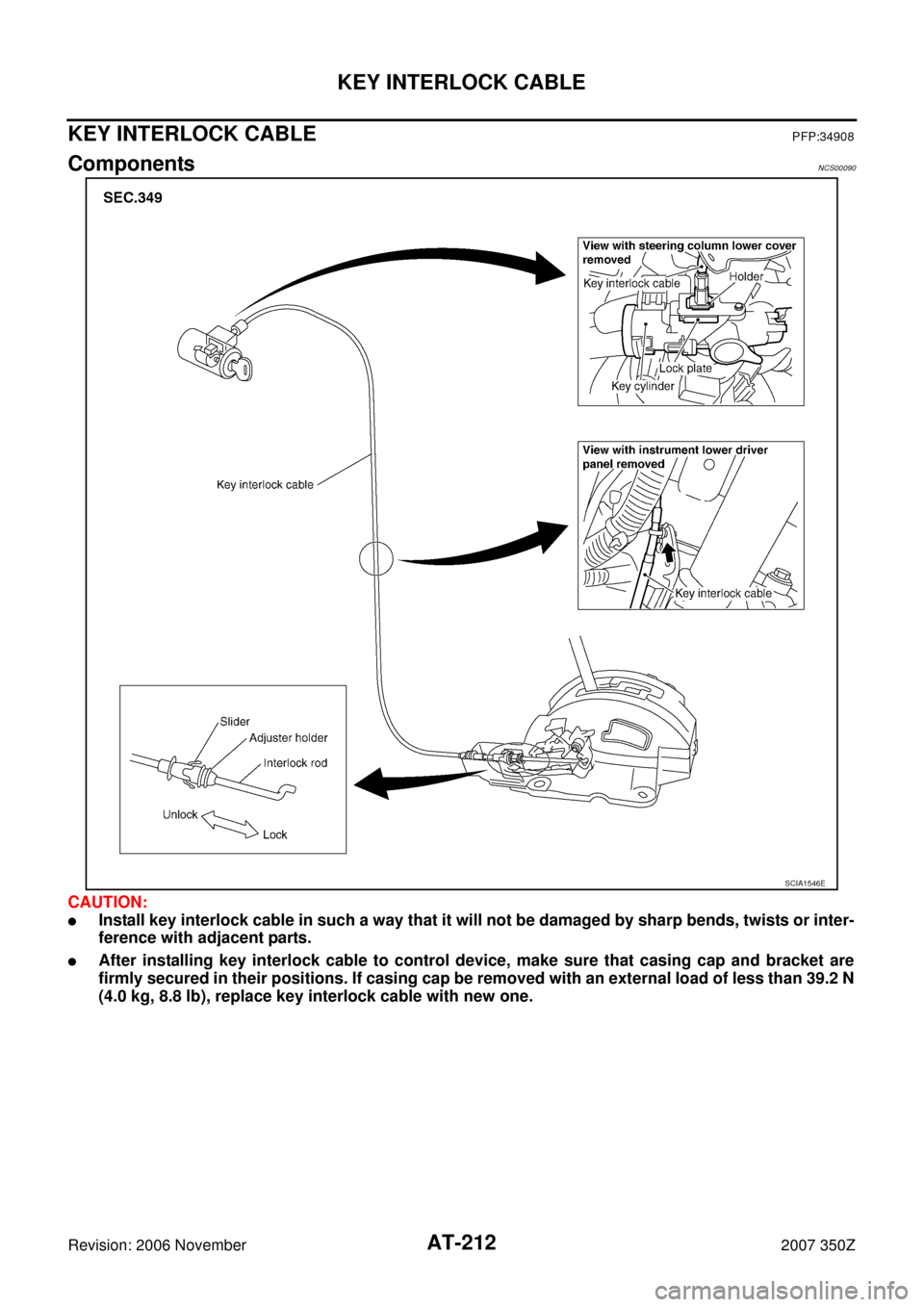
KEY INTERLOCK CABLEPFP:34908
ComponentsNCS00090
CAUTION:
�Install key interlock cable in such a way that it will not be damaged by sharp bends, twists or inter-
ference with adjacent parts.
�After installing key interlock cable to control device, make sure that casing cap and bracket are
firmly secured in their positions. If casing cap be removed with an external load of less than 39.2 N
(4.0 kg, 8.8 lb), replace key interlock cable with new one.
SCIA1546E
Page 220 of 312
AT-220
ON-VEHICLE SERVICE
Revision: 2006 November2007 350Z
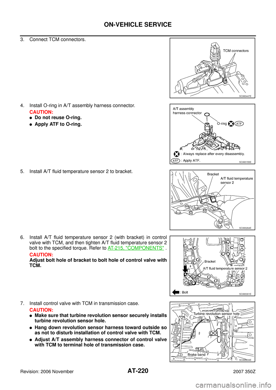
3. Connect TCM connectors.
4. Install O-ring in A/T assembly harness connector.
CAUTION:
�Do not reuse O-ring.
�Apply ATF to O-ring.
5. Install A/T fluid temperature sensor 2 to bracket.
6. Install A/T fluid temperature sensor 2 (with bracket) in control
valve with TCM, and then tighten A/T fluid temperature sensor 2
bolt to the specified torque. Refer to AT- 2 1 5 , "
COMPONENTS" .
CAUTION:
Adjust bolt hole of bracket to bolt hole of control valve with
TCM.
7. Install control valve with TCM in transmission case.
CAUTION:
�Make sure that turbine revolution sensor securely installs
turbine revolution sensor hole.
�Hang down revolution sensor harness toward outside so
as not to disturb installation of control valve with TCM.
�Adjust A/T assembly harness connector of control valve
with TCM to terminal hole of transmission case.
SCIA5447E
SCIA5155E
SCIA5264E
SCIA5301E
SCIA5034E
Page 221 of 312
ON-VEHICLE SERVICE
AT-221
D
E
F
G
H
I
J
K
L
MA
B
AT
Revision: 2006 November2007 350Z
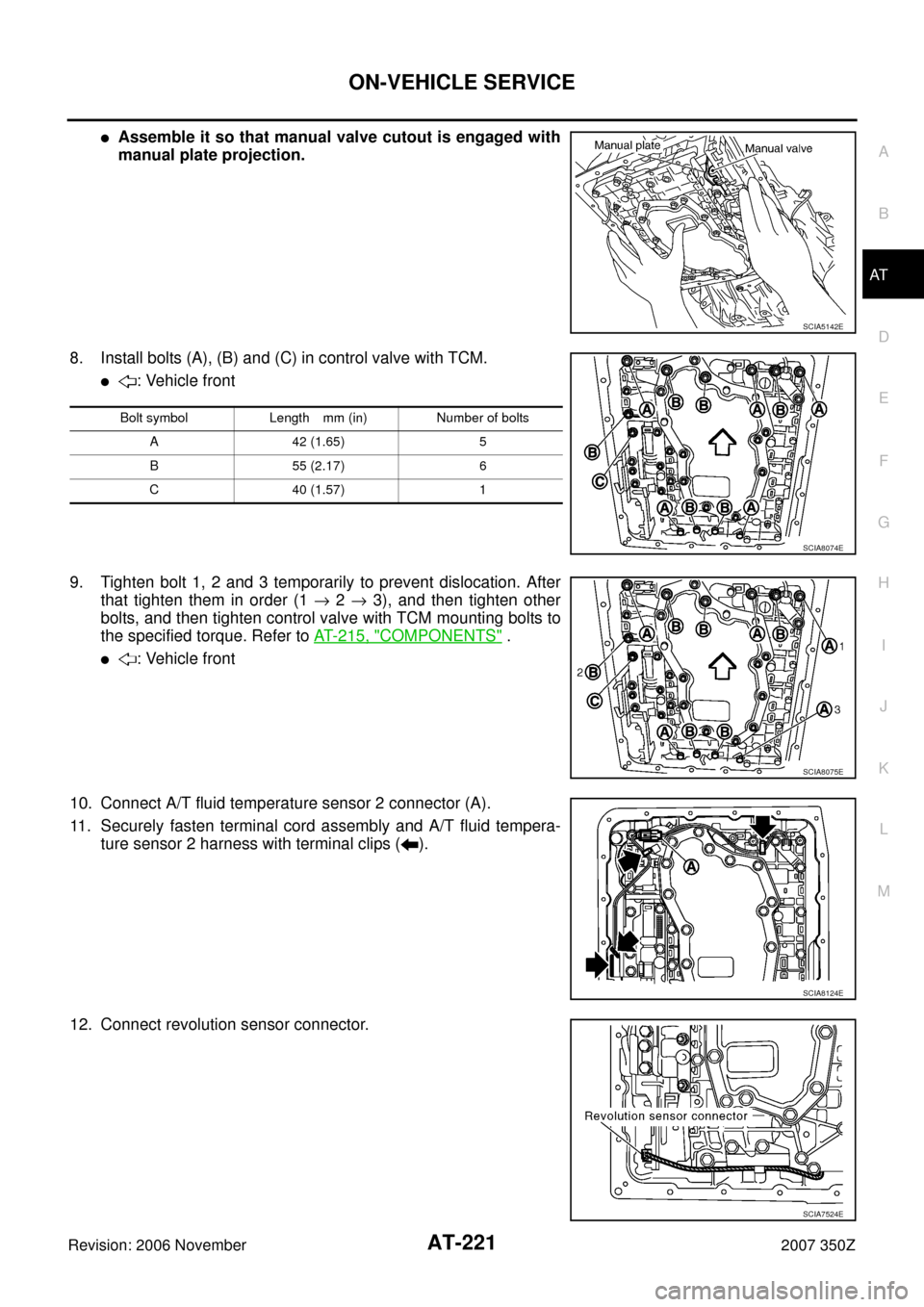
�Assemble it so that manual valve cutout is engaged with
manual plate projection.
8. Install bolts (A), (B) and (C) in control valve with TCM.
�: Vehicle front
9. Tighten bolt 1, 2 and 3 temporarily to prevent dislocation. After
that tighten them in order (1 → 2 → 3), and then tighten other
bolts, and then tighten control valve with TCM mounting bolts to
the specified torque. Refer to AT- 2 1 5 , "
COMPONENTS" .
�: Vehicle front
10. Connect A/T fluid temperature sensor 2 connector (A).
11. Securely fasten terminal cord assembly and A/T fluid tempera-
ture sensor 2 harness with terminal clips ( ).
12. Connect revolution sensor connector.
SCIA5142E
Bolt symbol Length mm (in) Number of bolts
A 42 (1.65) 5
B 55 (2.17) 6
C 40 (1.57) 1
SCIA8074E
SCIA8075E
SCIA8124E
SCIA7524E
Page 222 of 312

AT-222
ON-VEHICLE SERVICE
Revision: 2006 November2007 350Z
13. Securely fasten revolution sensor harness with terminal clip.
14. Install magnets in oil pan.
15. Install oil pan to transmission case.
a. Install oil pan gasket to oil pan.
CAUTION:
�Do not reuse oil pan gasket.
�Install it in the direction to align hole positions.
�Complete remove all moisture, oil and old gasket, etc. from oil pan gasket mounting surface.
b. Install oil pan (2) (with oil pan gasket) and clips (1) to transmis-
sion case.
�: Vehicle front
�: Oil pan mounting bolt
CAUTION:
�Install it so that drain plug (3) comes to the position as
shown in the figure.
�Be careful not to pinch harness.
�Complete remove all moisture, oil and old gasket, etc.
from oil pan mounting surface.
c. Tighten oil pan mounting bolts to the specified torque in numeri-
cal order shown in the figure after temporarily tightening them.
Refer to AT- 2 1 5 , "
COMPONENTS" .
CAUTION:
Do not reuse oil pan mounting bolts.
16. Install drain plug gasket and drain plug to oil pan, and then
tighten drain plug to the specified torque. Refer to AT- 2 1 5 ,
"COMPONENTS" .
CAUTION:
Do not reuse drain plug gasket.
SCIA7525E
SCIA5200E
SCIA8117E
SCIA4113E
Page 225 of 312

ON-VEHICLE SERVICE
AT-225
D
E
F
G
H
I
J
K
L
MA
B
AT
Revision: 2006 November2007 350Z
Installation
CAUTION:
After completing installation, check A/T fluid leakage and A/T fluid level. Refer to AT- 1 2 , "
Checking A/T
Fluid" .
1. Install A/T fluid temperature sensor 2 to bracket.
2. Install A/T fluid temperature sensor 2 (with bracket) in control
valve with TCM, and then tighten A/T fluid temperature sensor 2
bolt to the specified torque. Refer to AT- 2 1 5 , "
COMPONENTS" .
3. Connect A/T fluid temperature sensor 2 connector (1).
4. Securely fasten A/T fluid temperature sensor 2 harness with ter-
minal clip ( ).
5. Install oil pan to transmission case.
a. Install oil pan gasket to oil pan.
CAUTION:
�Do not reuse oil pan gasket.
�Install it in the direction to align hole positions.
�Complete remove all moisture, oil and old gasket, etc. from oil pan gasket mounting surface.
b. Install oil pan (2) (with oil pan gasket) and clips (1) to transmis-
sion case.
�: Vehicle front
�: Oil pan mounting bolt
CAUTION:
�Install it so that drain plug (3) comes to the position as
shown in the figure.
�Be careful not to pinch harness.
SCIA5264E
SCIA5302E
SCIA8076E
SCIA8117E
Page 238 of 312

AT-238
ON-VEHICLE SERVICE
Revision: 2006 November2007 350Z
INSTALLATION
CAUTION:
After completing installation, check A/T position, A/T fluid leakage and A/T fluid level. Refer to AT- 2 0 6 ,
"Checking of A/T Position" , AT- 1 2 , "Checking A/T Fluid" .
1. Install revolution sensor in transmission case, and then tighten a
revolution sensor mounting blot to the specified torque. Refer to
AT- 2 3 5 , "
COMPONENTS" .
CAUTION:
�Do not subject it to impact by dropping or hitting it.
�Do not disassemble.
�Do not allow metal filings, etc. to get on the sensor's front
edge magnetic area.
�Do not place in an area affected by magnetism.
2. Connect revolution sensor connector.
3. Securely fasten revolution sensor harness with clip.
4. Apply recommended sealant (Genuine Anaerobic Liquid Gasket
or equivalent. Refer to GI-45, "
Recommended Chemical Prod-
ucts and Sealants" .) to rear extension assembly as shown in
illustration.
CAUTION:
Completely remove all moisture, oil and old sealant, etc.
from transmission case and rear extension assembly
mounting surfaces.
SCIA3997E
SCIA7524E
SCIA7525E
SCIA8228E
Page 241 of 312

AIR BREATHER HOSE
AT-241
D
E
F
G
H
I
J
K
L
MA
B
AT
Revision: 2006 November2007 350Z
AIR BREATHER HOSEPFP:31098
Removal and InstallationNCS00096
Refer to the figure below for air breather hose removal and installation procedure.
CAUTION:
�When installing an air breather hose, do not to crush or block by folding or bending the hose.
�When inserting air breather hose to air breather tube, be sure to insert it fully until its end reaches
the tube bend R portion.
�Install A/T air breather hose to air breather tube so that the paint mark is facing upward.
�Ensure clips are securely installed to brackets when installing A/T breather hose to brackets.
�When inserting air breather hose to air breather box, be sure to insert it fully until its end reaches
the stop.
�Install A/T air breather hose to air breather box so that the paint mark is facing backward.
�Install clip (1) at the paint mark (A).
–Air breather hose (2)
–Harness (3)
1. Air breather box 2. Air breather hose 3. Clip
4. Clip 5. A/T fluid charging pipe
A. Air breather tube
SCIA8151E
SCIA8268E