Page 80 of 312

AT-80
TROUBLE DIAGNOSIS
Revision: 2006 November2007 350Z
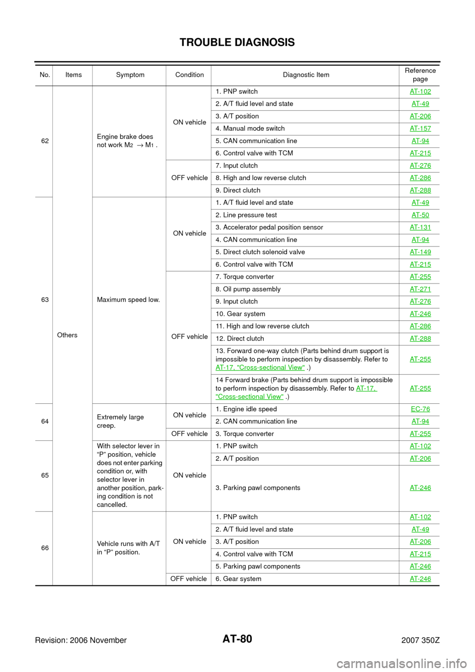
62
OthersEngine brake does
not work M2 → M1 .ON vehicle1. PNP switchAT- 1 0 2
2. A/T fluid level and stateAT- 4 9
3. A/T positionAT- 2 0 6
4. Manual mode switchAT- 1 5 7
5. CAN communication lineAT- 9 4
6. Control valve with TCMAT- 2 1 5
OFF vehicle7. Input clutchAT- 2 7 68. High and low reverse clutchAT- 2 8 6
9. Direct clutchAT- 2 8 8
63 Maximum speed low.ON vehicle1. A/T fluid level and stateAT- 4 9
2. Line pressure testAT- 5 0
3. Accelerator pedal position sensorAT- 1 3 1
4. CAN communication lineAT- 9 4
5. Direct clutch solenoid valveAT- 1 4 9
6. Control valve with TCMAT- 2 1 5
OFF vehicle7. Torque converterAT- 2 5 5
8. Oil pump assemblyAT- 2 7 1
9. Input clutchAT- 2 7 6
10. Gear systemAT- 2 4 6
11. High and low reverse clutchAT- 2 8 6
12. Direct clutchAT- 2 8 8
13. Forward one-way clutch (Parts behind drum support is
impossible to perform inspection by disassembly. Refer to
AT-17, "
Cross-sectional View" .)AT- 2 5 5
14 Forward brake (Parts behind drum support is impossible
to perform inspection by disassembly. Refer to AT-17,
"Cross-sectional View" .)AT- 2 5 5
64Extremely large
creep.ON vehicle1. Engine idle speed EC-76
2. CAN communication lineAT- 9 4
OFF vehicle 3. Torque converterAT- 2 5 5
65With selector lever in
“P” position, vehicle
does not enter parking
condition or, with
selector lever in
another position, park-
ing condition is not
cancelled.ON vehicle1. PNP switchAT- 1 0 2
2. A/T positionAT- 2 0 6
3. Parking pawl componentsAT- 2 4 6
66Vehicle runs with A/T
in “P” position.ON vehicle1. PNP switchAT- 1 0 2
2. A/T fluid level and stateAT- 4 9
3. A/T positionAT- 2 0 6
4. Control valve with TCMAT- 2 1 5
5. Parking pawl componentsAT- 2 4 6
OFF vehicle 6. Gear systemAT- 2 4 6
No. Items Symptom Condition Diagnostic ItemReference
page
Page 205 of 312

SHIFT CONTROL SYSTEM
AT-205
D
E
F
G
H
I
J
K
L
MA
B
AT
Revision: 2006 November2007 350Z
REMOVAL
CAUTION:
Make sure that parking brake is applied before removal/installation.
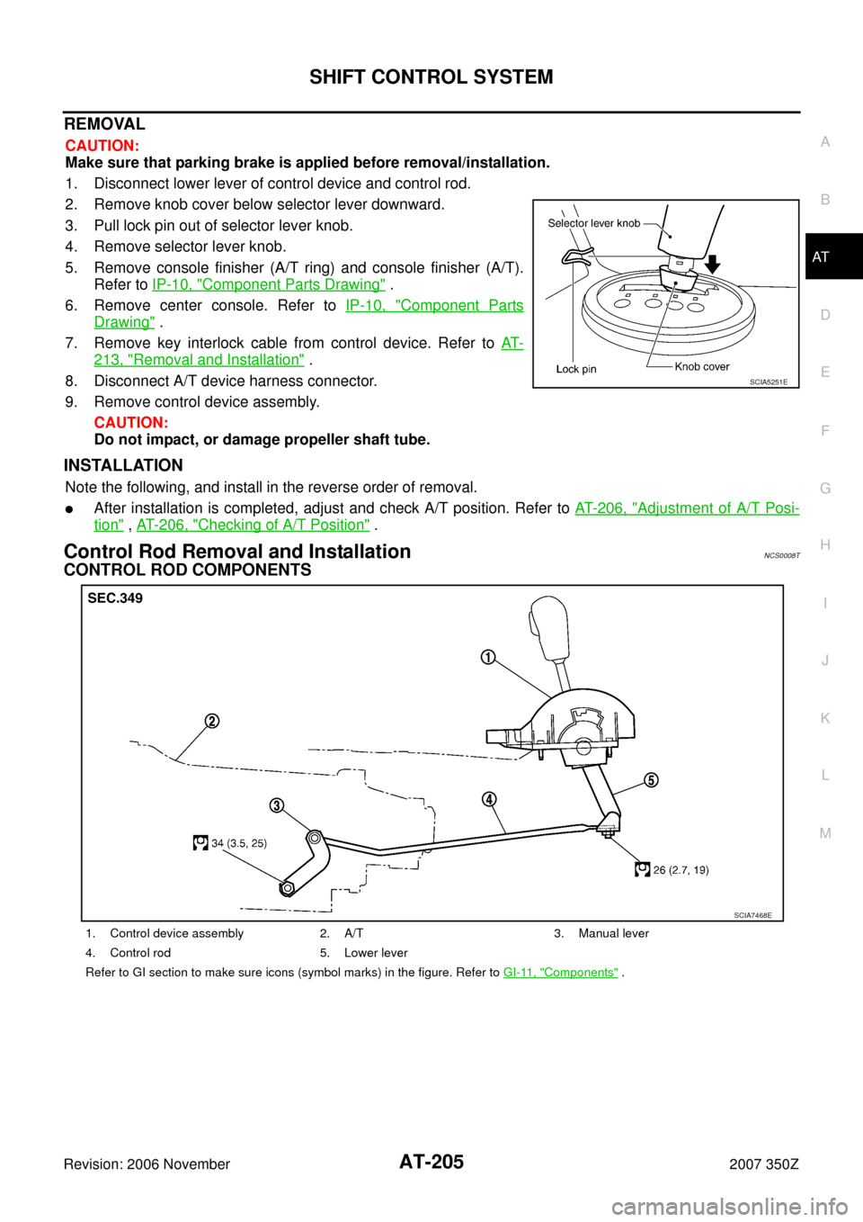
1. Disconnect lower lever of control device and control rod.
2. Remove knob cover below selector lever downward.
3. Pull lock pin out of selector lever knob.
4. Remove selector lever knob.
5. Remove console finisher (A/T ring) and console finisher (A/T).
Refer to IP-10, "
Component Parts Drawing" .
6. Remove center console. Refer to IP-10, "
Component Parts
Drawing" .
7. Remove key interlock cable from control device. Refer to AT-
213, "Removal and Installation" .
8. Disconnect A/T device harness connector.
9. Remove control device assembly.
CAUTION:
Do not impact, or damage propeller shaft tube.
INSTALLATION
Note the following, and install in the reverse order of removal.
�After installation is completed, adjust and check A/T position. Refer to AT- 2 0 6 , "Adjustment of A/T Posi-
tion" , AT- 2 0 6 , "Checking of A/T Position" .
Control Rod Removal and InstallationNCS0008T
CONTROL ROD COMPONENTS
SCIA5251E
1. Control device assembly 2. A/T 3. Manual lever
4. Control rod 5. Lower lever
Refer to GI section to make sure icons (symbol marks) in the figure. Refer to GI-11, "
Components" .
SCIA7468E
Page 295 of 312

ASSEMBLY
AT-295
D
E
F
G
H
I
J
K
L
MA
B
AT
Revision: 2006 November2007 350Z
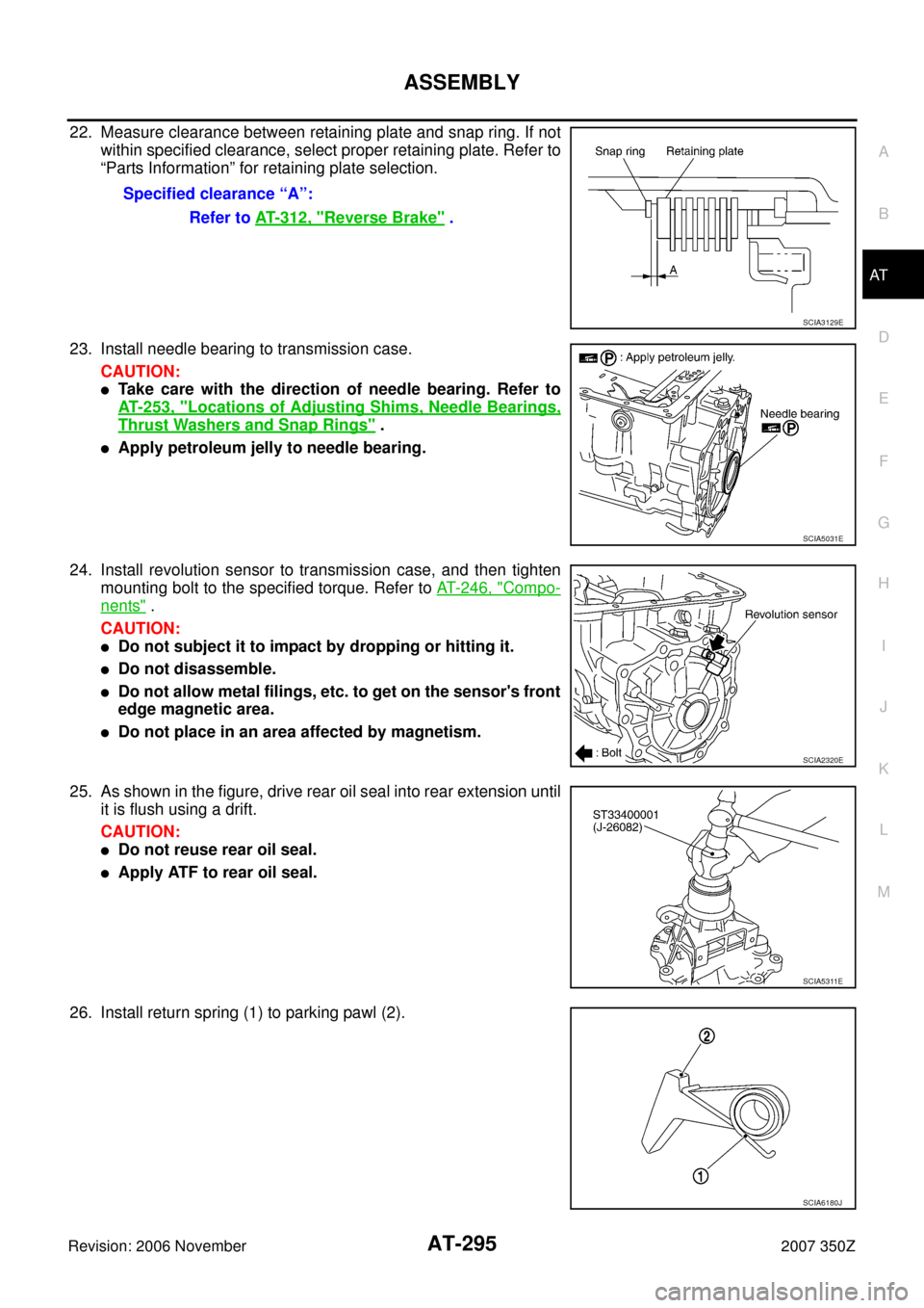
22. Measure clearance between retaining plate and snap ring. If not
within specified clearance, select proper retaining plate. Refer to
“Parts Information” for retaining plate selection.
23. Install needle bearing to transmission case.
CAUTION:
�Take care with the direction of needle bearing. Refer to
AT- 2 5 3 , "
Locations of Adjusting Shims, Needle Bearings,
Thrust Washers and Snap Rings" .
�Apply petroleum jelly to needle bearing.
24. Install revolution sensor to transmission case, and then tighten
mounting bolt to the specified torque. Refer to AT- 2 4 6 , "
Compo-
nents" .
CAUTION:
�Do not subject it to impact by dropping or hitting it.
�Do not disassemble.
�Do not allow metal filings, etc. to get on the sensor's front
edge magnetic area.
�Do not place in an area affected by magnetism.
25. As shown in the figure, drive rear oil seal into rear extension until
it is flush using a drift.
CAUTION:
�Do not reuse rear oil seal.
�Apply ATF to rear oil seal.
26. Install return spring (1) to parking pawl (2).Specified clearance “A”:
Refer to AT- 3 1 2 , "
Reverse Brake" .
SCIA3129E
SCIA5031E
SCIA2320E
SCIA5311E
SCIA6180J
Page:
< prev 1-8 9-16 17-24