Page 25 of 312
A/T CONTROL SYSTEM
AT-25
D
E
F
G
H
I
J
K
L
MA
B
AT
Revision: 2006 November2007 350Z
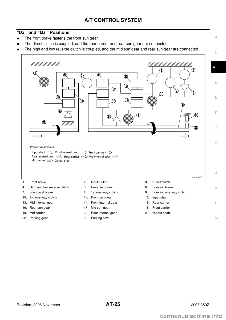
“D3 ” and “M3 ” Positions
�The front brake fastens the front sun gear.
�The direct clutch is coupled, and the rear carrier and rear sun gear are connected.
�The high and low reverse clutch is coupled, and the mid sun gear and rear sun gear are connected.
1. Front brake 2. Input clutch 3. Direct clutch
4. High and low reverse clutch 5. Reverse brake 6. Forward brake
7. Low coast brake 8. 1st one-way clutch 9. Forward one-way clutch
10. 3rd one-way clutch 11. Front sun gear 12. Input shaft
13. Mid internal gear 14. Front internal gear 15. Rear carrier
16. Rear sun gear 17. Mid sun gear 18. Front carrier
19. Mid carrier 20. Rear internal gear 21. Output shaft
22. Parking gear 23. Parking pawl
SCIA1516E
Page 26 of 312
AT-26
A/T CONTROL SYSTEM
Revision: 2006 November2007 350Z
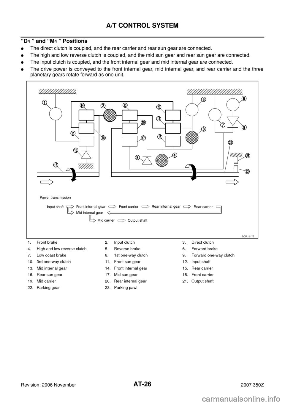
“D4 ” and “M4 ” Positions
�The direct clutch is coupled, and the rear carrier and rear sun gear are connected.
�The high and low reverse clutch is coupled, and the mid sun gear and rear sun gear are connected.
�The input clutch is coupled, and the front internal gear and mid internal gear are connected.
�The drive power is conveyed to the front internal gear, mid internal gear, and rear carrier and the three
planetary gears rotate forward as one unit.
1. Front brake 2. Input clutch 3. Direct clutch
4. High and low reverse clutch 5. Reverse brake 6. Forward brake
7. Low coast brake 8. 1st one-way clutch 9. Forward one-way clutch
10. 3rd one-way clutch 11. Front sun gear 12. Input shaft
13. Mid internal gear 14. Front internal gear 15. Rear carrier
16. Rear sun gear 17. Mid sun gear 18. Front carrier
19. Mid carrier 20. Rear internal gear 21. Output shaft
22. Parking gear 23. Parking pawl
SCIA1517E
Page 27 of 312
A/T CONTROL SYSTEM
AT-27
D
E
F
G
H
I
J
K
L
MA
B
AT
Revision: 2006 November2007 350Z
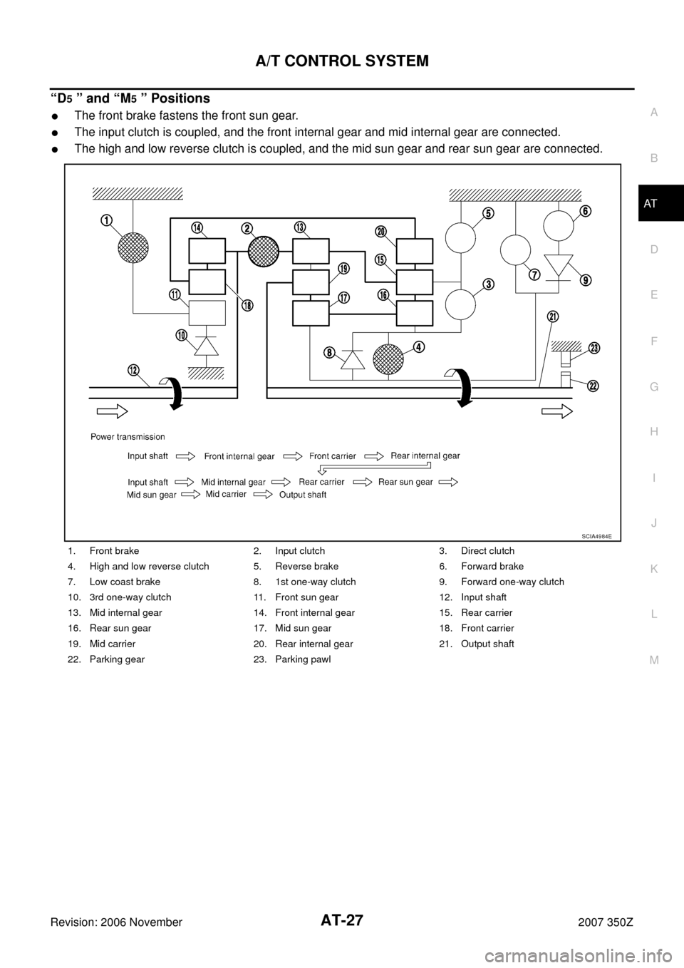
“D5 ” and “M5 ” Positions
�The front brake fastens the front sun gear.
�The input clutch is coupled, and the front internal gear and mid internal gear are connected.
�The high and low reverse clutch is coupled, and the mid sun gear and rear sun gear are connected.
1. Front brake 2. Input clutch 3. Direct clutch
4. High and low reverse clutch 5. Reverse brake 6. Forward brake
7. Low coast brake 8. 1st one-way clutch 9. Forward one-way clutch
10. 3rd one-way clutch 11. Front sun gear 12. Input shaft
13. Mid internal gear 14. Front internal gear 15. Rear carrier
16. Rear sun gear 17. Mid sun gear 18. Front carrier
19. Mid carrier 20. Rear internal gear 21. Output shaft
22. Parking gear 23. Parking pawl
SCIA4984E
Page 28 of 312
AT-28
A/T CONTROL SYSTEM
Revision: 2006 November2007 350Z
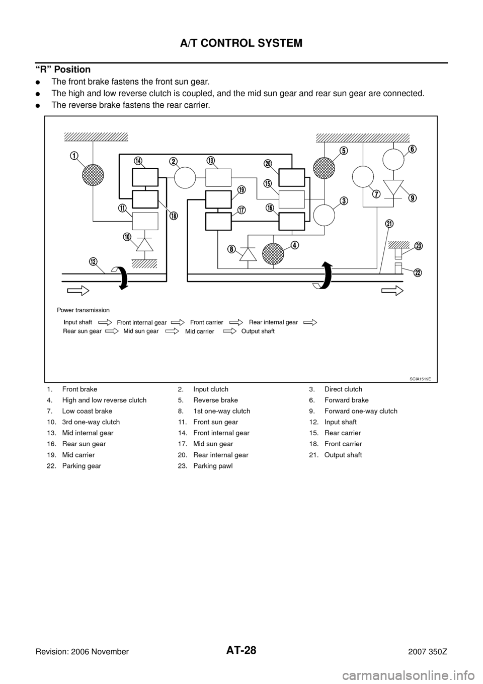
“R” Position
�The front brake fastens the front sun gear.
�The high and low reverse clutch is coupled, and the mid sun gear and rear sun gear are connected.
�The reverse brake fastens the rear carrier.
1. Front brake 2. Input clutch 3. Direct clutch
4. High and low reverse clutch 5. Reverse brake 6. Forward brake
7. Low coast brake 8. 1st one-way clutch 9. Forward one-way clutch
10. 3rd one-way clutch 11. Front sun gear 12. Input shaft
13. Mid internal gear 14. Front internal gear 15. Rear carrier
16. Rear sun gear 17. Mid sun gear 18. Front carrier
19. Mid carrier 20. Rear internal gear 21. Output shaft
22. Parking gear 23. Parking pawl
SCIA1519E
Page 49 of 312

TROUBLE DIAGNOSIS
AT-49
D
E
F
G
H
I
J
K
L
MA
B
AT
Revision: 2006 November2007 350Z
Inspections Before Trouble DiagnosisNCS00024
A/T FLUID CHECK
A/T Fluid Leakage and A/T Fluid Level Check
Inspect for A/T fluid leakage and check the A/T fluid level. Refer to AT- 1 2 , "Checking A/T Fluid" .
A/T Fluid Condition Check
Inspect the A/T fluid condition.
STALL TEST
Stall Test Procedure
1. Inspect the amount of engine oil. Replenish the engine oil if necessary.
2. Drive for about 10 minutes to warm up the vehicle so that the A/
T fluid temperature is 50 to 80°C (122 to 176°F). Inspect the
amount of ATF. Replenish if necessary.
3. Securely engage the parking brake so that the tires do not turn.
4. Engine start, apply foot brake, and place selector lever in “D”
position.
5. While holding down the foot brake, gradually press down accel-
erator pedal.
6. Quickly read off the stall speed, then quickly remove your foot
from accelerator pedal.
CAUTION:
Do not hold down accelerator pedal for more than 5 sec-
onds during this test.
7. Move selector lever to “N” position.
Fluid condition Conceivable Cause Required Operation
Varnished (viscous
varnish state)Clutch, brake
scorchedReplace the ATF and check the A/
T main unit and the vehicle for
malfunctions (wire harnesses,
cooler pipes, etc.)
Milky white or cloudy Water in the fluidReplace the ATF and check for
places where water is getting in.
Large amount of metal
powder mixed inUnusual wear of
sliding parts within
A/TReplace the ATF and check for
improper operation of the A/T.
SAT638A
SAT647B
SAT513G
Stall speed: 2,700 – 3,000 rpm
SAT514G
Page 51 of 312
![NISSAN 350Z 2007 Z33 Automatic Transmission Workshop Manual TROUBLE DIAGNOSIS
AT-51
D
E
F
G
H
I
J
K
L
MA
B
AT
Revision: 2006 November2007 350Z
3. After warming up remove the oil pressure detection plug and
install the oil pressure gauge [ST2505S001(J-34301-C)]](/manual-img/5/755/w960_755-50.png "NISSAN 350Z 2007 Z33 Automatic Transmission Workshop Manual TROUBLE DIAGNOSIS
AT-51
D
E
F
G
H
I
J
K
L
MA
B
AT
Revision: 2006 November2007 350Z
3. After warming up remove the oil pressure detection plug and
install the oil pressure gauge [ST2505S001(J-34301-C)]")
TROUBLE DIAGNOSIS
AT-51
D
E
F
G
H
I
J
K
L
MA
B
AT
Revision: 2006 November2007 350Z
3. After warming up remove the oil pressure detection plug and
install the oil pressure gauge [ST2505S001(J-34301-C)].
CAUTION:
When using the oil pressure gauge, be sure to use O- ring
attached to the oil pressure detection plug.
4. Securely engage the parking brake so that the tires do not turn.
5. Start the engine, then measure the line pressure at both idle and
the stall speed.
CAUTION:
�Keep brake pedal pressed all the way down during mea-
surement.
�When measuring the line pressure at the stall speed,
refer to AT- 4 9 , "
STALL TEST" .
6. After the measurements are complete, install the oil pressure
detection plug and tighten to the specified torque. Refer to AT-
246, "Components" .
CAUTION:
� Do not reuse O-ring.
� Apply ATF to O-ring.
Line Pressure
SCIA5309E
SAT513G
SAT493G
Engine speedLine pressure kPa (kg/cm2 , psi)
“R” position “D” and “M” positions
At idle speed 425 – 465 (4.3 – 4.7, 62 – 67) 379 – 428 (3.9 – 4.4, 55 – 62)
At stall speed 1,605 – 1,950 (16.4 – 19.9, 233 – 283) 1,310 – 1,500 (13.4 – 15.3, 190 – 218)
Page 53 of 312

TROUBLE DIAGNOSIS
AT-53
D
E
F
G
H
I
J
K
L
MA
B
AT
Revision: 2006 November2007 350Z
Check Before Engine is StartedNCS00025
1. CHECK A/T CHECK INDICATOR LAMP
1. Park vehicle on level surface.
2. Move selector lever to “P” position.
3. Turn ignition switch OFF and wait at least 10 seconds.
4. Turn ignition switch ON. (Do not start engine.)
Does A/T CHECK indicator lamp light up for about 2 seconds?
YES >> 1. Turn ignition switch OFF.
2. Perform self-diagnostics and record all NG items on the AT- 4 4 , "
DIAGNOSTIC WORKSHEET"
. Refer to AT- 8 6 , "SELF-DIAGNOSTIC RESULT MODE" , AT- 9 2 , "Diagnostic Procedure With-
out CONSULT-III" .
3. Go to AT- 5 3 , "
Check at Idle" .
NO >> Stop the road test and go to AT- 1 7 2 , "
A/T Check Indicator Lamp Does Not Come On" .
Check at IdleNCS00026
1. CHECK STARTING THE ENGINE
1. Park vehicle on level surface.
2. Move selector lever to “P” or “N” position.
3. Turn ignition switch OFF.
4. Start engine.
Does the engine start?
YES >> GO TO 2.
NO >> Stop the road test and go to AT- 1 7 3 , "
Engine Cannot Be Started in “P” or “N” Position" .
2. CHECK STARTING THE ENGINE
1. Turn ignition switch ON. (Do not start engine.)
2. Move selector lever in “D”, “M” or “R” position.
3. Start engine.
Does the engine start in each position?
YES >> Stop the road test and go to AT- 1 7 3 , "Engine Cannot Be Started in “P” or “N” Position" .
NO >> GO TO 3.
3. CHECK “P” POSITION FUNCTIONS
1. Move selector lever to “P” position.
2. Turn ignition switch OFF.
3. Release the parking brake.
4. Push the vehicle forward or backward.
5. Engage the parking brake.
When you push the vehicle with disengaging the parking brake, does it move?
YES >> Enter a check mark at AT- 1 7 3 , "In “P” Position, Vehicle Moves When Pushed" on the AT- 4 4 ,
"DIAGNOSTIC WORKSHEET" , then continue the road test.
NO >> GO TO 4.
Page 54 of 312

AT-54
TROUBLE DIAGNOSIS
Revision: 2006 November2007 350Z
4. CHECK “N” POSITION FUNCTIONS
1. Start engine.
2. Move selector lever to “N” position.
3. Release the parking brake.
Does vehicle move forward or backward?
YES >> Enter a check mark at AT- 1 7 4 , "In “N” Position, Vehicle Moves" on the AT- 4 4 , "DIAGNOSTIC
WORKSHEET" , then continue the road test.
NO >> GO TO 5.
5. CHECK SHIFT SHOCK
1. Engage the brake.
2. Move selector lever to “D” position.
When the A/T is shifted from
“N” to “D”, is there an excessive shock?
YES >> Enter a check mark at AT- 1 7 5 , "Large Shock (“N” to “D” Position)" on the AT- 4 4 , "DIAGNOSTIC
WORKSHEET" , then continue the road test.
NO >> GO TO 6.
6. CHECK “R” POSITION FUNCTIONS
1. Engage the brake.
2. Move selector lever to “R” position.
3. Release the brake for 4 to 5 seconds.
Does the vehicle creep backward?
YES >> GO TO 7.
NO >> Enter a check mark at AT- 1 7 7 , "
Vehicle Does Not Creep Backward in “R” Position" on the AT- 4 4 ,
"DIAGNOSTIC WORKSHEET" , then continue the road test.
7. CHECK “D” POSITION FUNCTIONS
Inspect whether the vehicle creep forward when the A/T is put into the “D” position.
Does the vehicle creep forward in the
“D” position?
YES >> Go to AT- 5 5 , "Cruise Test — Part 1" , AT- 5 7 , "Cruise Test — Part 2" and AT- 5 8 , "Cruise Test —
Part 3" .
NO >> Enter a check mark at AT- 1 7 9 , "
Vehicle Does Not Creep Forward in “D” Position" on the AT- 4 4 ,
"DIAGNOSTIC WORKSHEET" , then continue the road test. Go to AT- 5 5 , "Cruise Test — Part 1"
, AT- 5 7 , "Cruise Test — Part 2" and AT- 5 8 , "Cruise Test — Part 3" .