2007 NISSAN 350Z check transmission fluid
[x] Cancel search: check transmission fluidPage 148 of 312
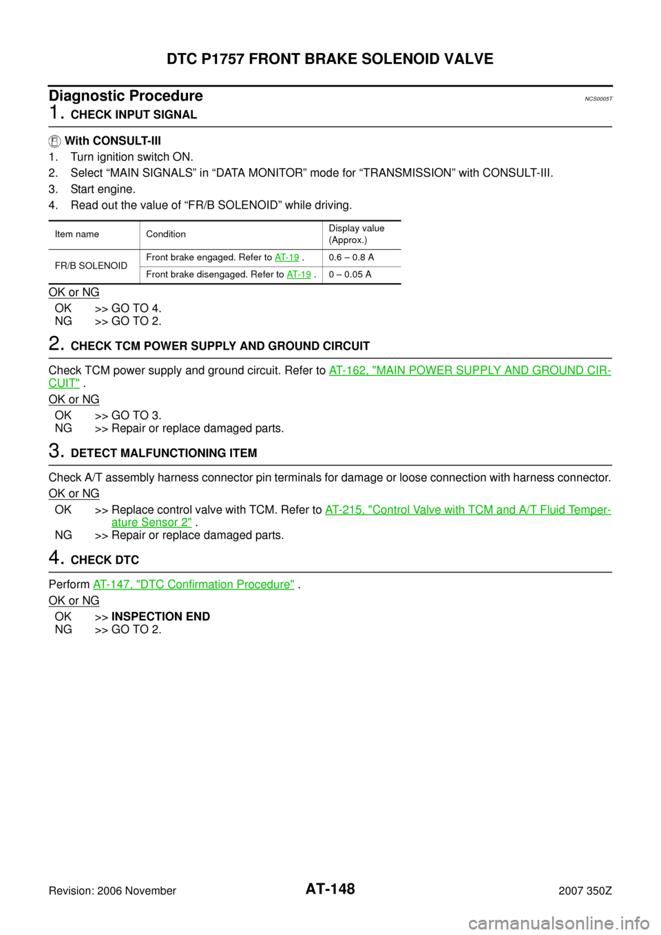
AT-148
DTC P1757 FRONT BRAKE SOLENOID VALVE
Revision: 2006 November2007 350Z
Diagnostic ProcedureNCS0005T
1. CHECK INPUT SIGNAL
With CONSULT-III
1. Turn ignition switch ON.
2. Select “MAIN SIGNALS” in “DATA MONITOR” mode for “TRANSMISSION” with CONSULT-III.
3. Start engine.
4. Read out the value of “FR/B SOLENOID” while driving.
OK or NG
OK >> GO TO 4.
NG >> GO TO 2.
2. CHECK TCM POWER SUPPLY AND GROUND CIRCUIT
Check TCM power supply and ground circuit. Refer to AT- 1 6 2 , "
MAIN POWER SUPPLY AND GROUND CIR-
CUIT" .
OK or NG
OK >> GO TO 3.
NG >> Repair or replace damaged parts.
3. DETECT MALFUNCTIONING ITEM
Check A/T assembly harness connector pin terminals for damage or loose connection with harness connector.
OK or NG
OK >> Replace control valve with TCM. Refer to AT- 2 1 5 , "Control Valve with TCM and A/T Fluid Temper-
ature Sensor 2" .
NG >> Repair or replace damaged parts.
4. CHECK DTC
Perform AT- 1 4 7 , "
DTC Confirmation Procedure" .
OK or NG
OK >>INSPECTION END
NG >> GO TO 2.
Item name ConditionDisplay value
(Approx.)
FR/B SOLENOIDFront brake engaged. Refer to AT- 1 9
. 0.6 – 0.8 A
Front brake disengaged. Refer to AT- 1 9
. 0 – 0.05 A
Page 150 of 312
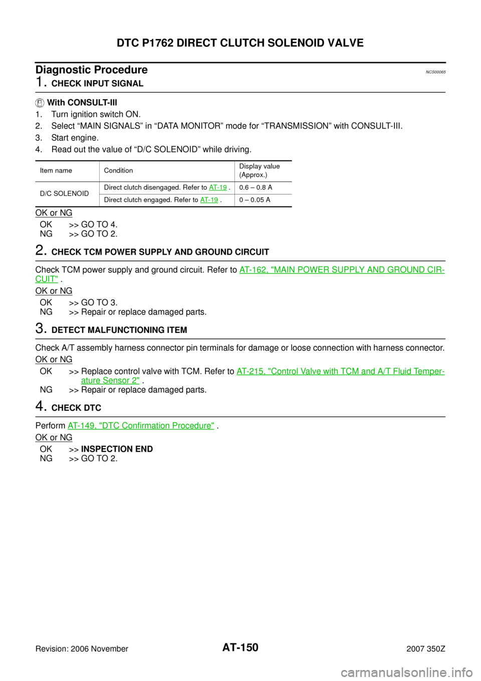
AT-150
DTC P1762 DIRECT CLUTCH SOLENOID VALVE
Revision: 2006 November2007 350Z
Diagnostic ProcedureNCS00065
1. CHECK INPUT SIGNAL
With CONSULT-III
1. Turn ignition switch ON.
2. Select “MAIN SIGNALS” in “DATA MONITOR” mode for “TRANSMISSION” with CONSULT-III.
3. Start engine.
4. Read out the value of “D/C SOLENOID” while driving.
OK or NG
OK >> GO TO 4.
NG >> GO TO 2.
2. CHECK TCM POWER SUPPLY AND GROUND CIRCUIT
Check TCM power supply and ground circuit. Refer to AT- 1 6 2 , "
MAIN POWER SUPPLY AND GROUND CIR-
CUIT" .
OK or NG
OK >> GO TO 3.
NG >> Repair or replace damaged parts.
3. DETECT MALFUNCTIONING ITEM
Check A/T assembly harness connector pin terminals for damage or loose connection with harness connector.
OK or NG
OK >> Replace control valve with TCM. Refer to AT- 2 1 5 , "Control Valve with TCM and A/T Fluid Temper-
ature Sensor 2" .
NG >> Repair or replace damaged parts.
4. CHECK DTC
Perform AT- 1 4 9 , "
DTC Confirmation Procedure" .
OK or NG
OK >>INSPECTION END
NG >> GO TO 2.
Item name ConditionDisplay value
(Approx.)
D/C SOLENOIDDirect clutch disengaged. Refer to AT- 1 9
. 0.6 – 0.8 A
Direct clutch engaged. Refer to AT- 1 9
. 0 – 0.05 A
Page 152 of 312
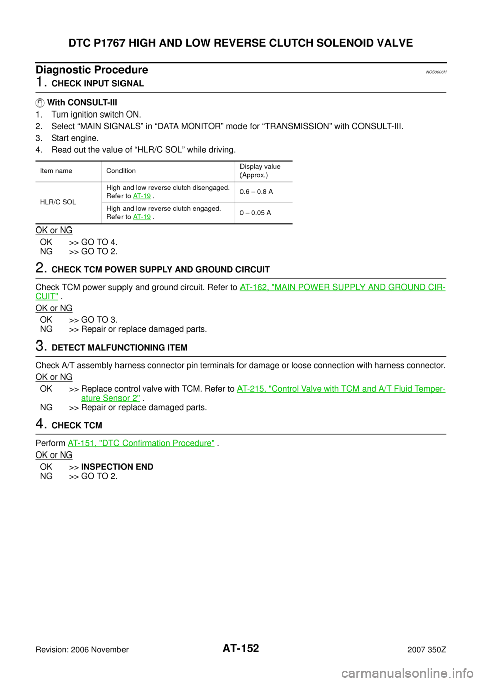
AT-152
DTC P1767 HIGH AND LOW REVERSE CLUTCH SOLENOID VALVE
Revision: 2006 November2007 350Z
Diagnostic ProcedureNCS0006H
1. CHECK INPUT SIGNAL
With CONSULT-III
1. Turn ignition switch ON.
2. Select “MAIN SIGNALS” in “DATA MONITOR” mode for “TRANSMISSION” with CONSULT-III.
3. Start engine.
4. Read out the value of “HLR/C SOL” while driving.
OK or NG
OK >> GO TO 4.
NG >> GO TO 2.
2. CHECK TCM POWER SUPPLY AND GROUND CIRCUIT
Check TCM power supply and ground circuit. Refer to AT- 1 6 2 , "
MAIN POWER SUPPLY AND GROUND CIR-
CUIT" .
OK or NG
OK >> GO TO 3.
NG >> Repair or replace damaged parts.
3. DETECT MALFUNCTIONING ITEM
Check A/T assembly harness connector pin terminals for damage or loose connection with harness connector.
OK or NG
OK >> Replace control valve with TCM. Refer to AT- 2 1 5 , "Control Valve with TCM and A/T Fluid Temper-
ature Sensor 2" .
NG >> Repair or replace damaged parts.
4. CHECK TCM
Perform AT- 1 5 1 , "
DTC Confirmation Procedure" .
OK or NG
OK >>INSPECTION END
NG >> GO TO 2.
Item name ConditionDisplay value
(Approx.)
HLR/C SOLHigh and low reverse clutch disengaged.
Refer to AT- 1 9
.0.6 – 0.8 A
High and low reverse clutch engaged.
Refer to AT- 1 9
.0 – 0.05 A
Page 154 of 312
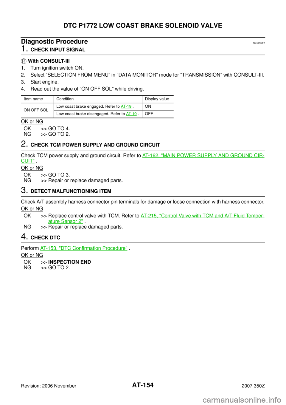
AT-154
DTC P1772 LOW COAST BRAKE SOLENOID VALVE
Revision: 2006 November2007 350Z
Diagnostic ProcedureNCS0006T
1. CHECK INPUT SIGNAL
With CONSULT-III
1. Turn ignition switch ON.
2. Select “SELECTION FROM MENU” in “DATA MONITOR” mode for “TRANSMISSION” with CONSULT-III.
3. Start engine.
4. Read out the value of “ON OFF SOL” while driving.
OK or NG
OK >> GO TO 4.
NG >> GO TO 2.
2. CHECK TCM POWER SUPPLY AND GROUND CIRCUIT
Check TCM power supply and ground circuit. Refer to AT- 1 6 2 , "
MAIN POWER SUPPLY AND GROUND CIR-
CUIT" .
OK or NG
OK >> GO TO 3.
NG >> Repair or replace damaged parts.
3. DETECT MALFUNCTIONING ITEM
Check A/T assembly harness connector pin terminals for damage or loose connection with harness connector.
OK or NG
OK >> Replace control valve with TCM. Refer to AT- 2 1 5 , "Control Valve with TCM and A/T Fluid Temper-
ature Sensor 2" .
NG >> Repair or replace damaged parts.
4. CHECK DTC
Perform AT- 1 5 3 , "
DTC Confirmation Procedure" .
OK or NG
OK >>INSPECTION END
NG >> GO TO 2.
Item name Condition Display value
ON OFF SOLLow coast brake engaged. Refer to AT- 1 9
.ON
Low coast brake disengaged. Refer to AT- 1 9
.OFF
Page 156 of 312
AT-156
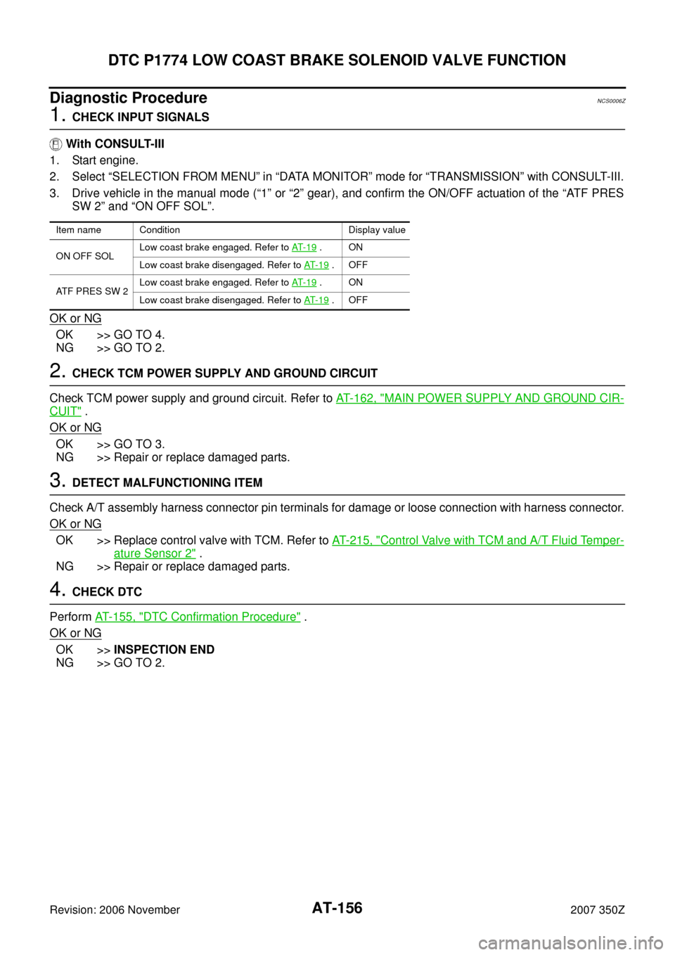
DTC P1774 LOW COAST BRAKE SOLENOID VALVE FUNCTION
Revision: 2006 November2007 350Z
Diagnostic ProcedureNCS0006Z
1. CHECK INPUT SIGNALS
With CONSULT-III
1. Start engine.
2. Select “SELECTION FROM MENU” in “DATA MONITOR” mode for “TRANSMISSION” with CONSULT-III.
3. Drive vehicle in the manual mode (“1” or “2” gear), and confirm the ON/OFF actuation of the “ATF PRES
SW 2” and “ON OFF SOL”.
OK or NG
OK >> GO TO 4.
NG >> GO TO 2.
2. CHECK TCM POWER SUPPLY AND GROUND CIRCUIT
Check TCM power supply and ground circuit. Refer to AT- 1 6 2 , "
MAIN POWER SUPPLY AND GROUND CIR-
CUIT" .
OK or NG
OK >> GO TO 3.
NG >> Repair or replace damaged parts.
3. DETECT MALFUNCTIONING ITEM
Check A/T assembly harness connector pin terminals for damage or loose connection with harness connector.
OK or NG
OK >> Replace control valve with TCM. Refer to AT- 2 1 5 , "Control Valve with TCM and A/T Fluid Temper-
ature Sensor 2" .
NG >> Repair or replace damaged parts.
4. CHECK DTC
Perform AT- 1 5 5 , "
DTC Confirmation Procedure" .
OK or NG
OK >>INSPECTION END
NG >> GO TO 2.
Item name Condition Display value
ON OFF SOLLow coast brake engaged. Refer to AT- 1 9
.ON
Low coast brake disengaged. Refer to AT- 1 9
.OFF
ATF PRES SW 2Low coast brake engaged. Refer to AT- 1 9
.ON
Low coast brake disengaged. Refer to AT- 1 9
.OFF
Page 176 of 312
AT-176
TROUBLE DIAGNOSIS FOR SYMPTOMS
Revision: 2006 November2007 350Z
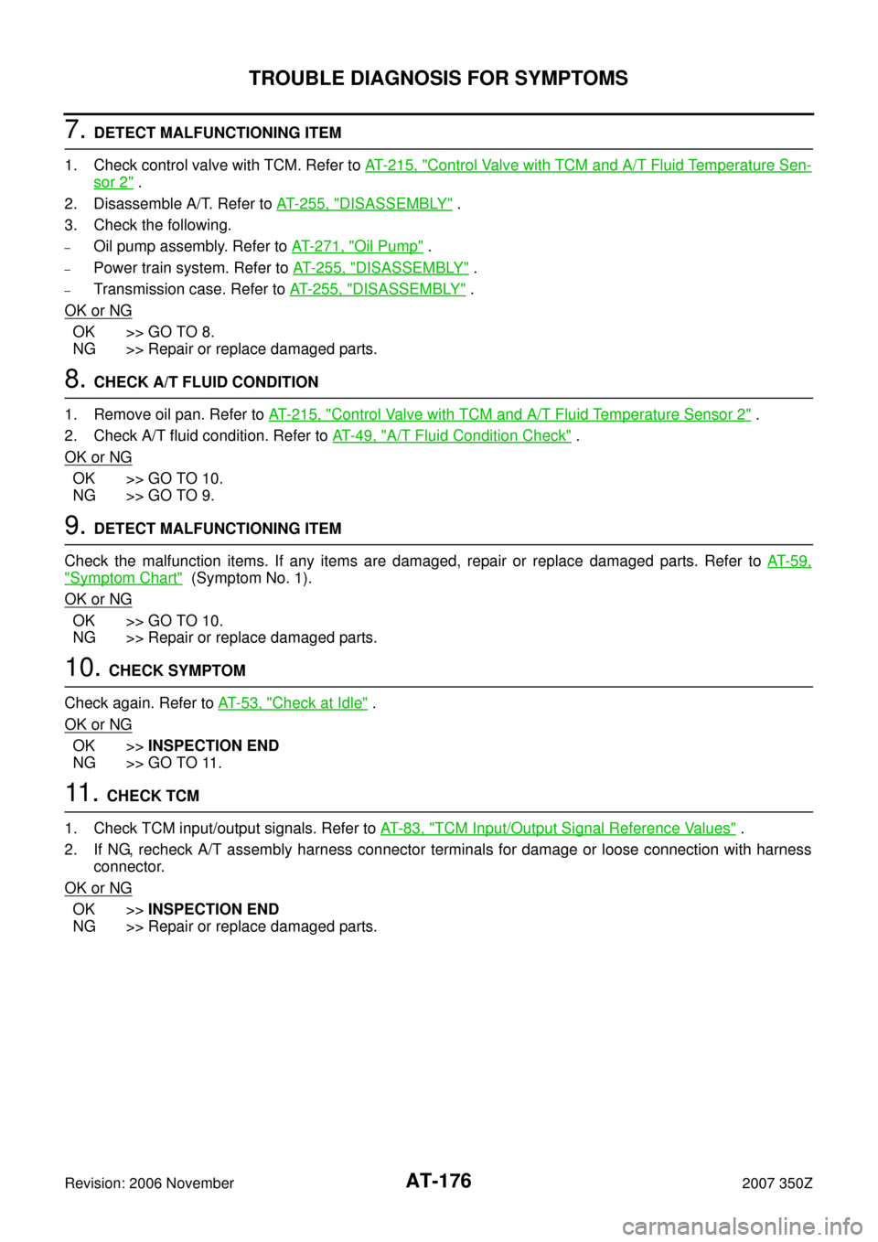
7. DETECT MALFUNCTIONING ITEM
1. Check control valve with TCM. Refer to AT- 2 1 5 , "
Control Valve with TCM and A/T Fluid Temperature Sen-
sor 2" .
2. Disassemble A/T. Refer to AT- 2 5 5 , "
DISASSEMBLY" .
3. Check the following.
–Oil pump assembly. Refer to AT- 2 7 1 , "Oil Pump" .
–Power train system. Refer to AT- 2 5 5 , "DISASSEMBLY" .
–Transmission case. Refer to AT- 2 5 5 , "DISASSEMBLY" .
OK or NG
OK >> GO TO 8.
NG >> Repair or replace damaged parts.
8. CHECK A/T FLUID CONDITION
1. Remove oil pan. Refer to AT- 2 1 5 , "
Control Valve with TCM and A/T Fluid Temperature Sensor 2" .
2. Check A/T fluid condition. Refer to AT- 4 9 , "
A/T Fluid Condition Check" .
OK or NG
OK >> GO TO 10.
NG >> GO TO 9.
9. DETECT MALFUNCTIONING ITEM
Check the malfunction items. If any items are damaged, repair or replace damaged parts. Refer to AT- 5 9 ,
"Symptom Chart" (Symptom No. 1).
OK or NG
OK >> GO TO 10.
NG >> Repair or replace damaged parts.
10. CHECK SYMPTOM
Check again. Refer to AT- 5 3 , "
Check at Idle" .
OK or NG
OK >>INSPECTION END
NG >> GO TO 11.
11 . CHECK TCM
1. Check TCM input/output signals. Refer to AT- 8 3 , "
TCM Input/Output Signal Reference Values" .
2. If NG, recheck A/T assembly harness connector terminals for damage or loose connection with harness
connector.
OK or NG
OK >>INSPECTION END
NG >> Repair or replace damaged parts.
Page 178 of 312
AT-178
TROUBLE DIAGNOSIS FOR SYMPTOMS
Revision: 2006 November2007 350Z
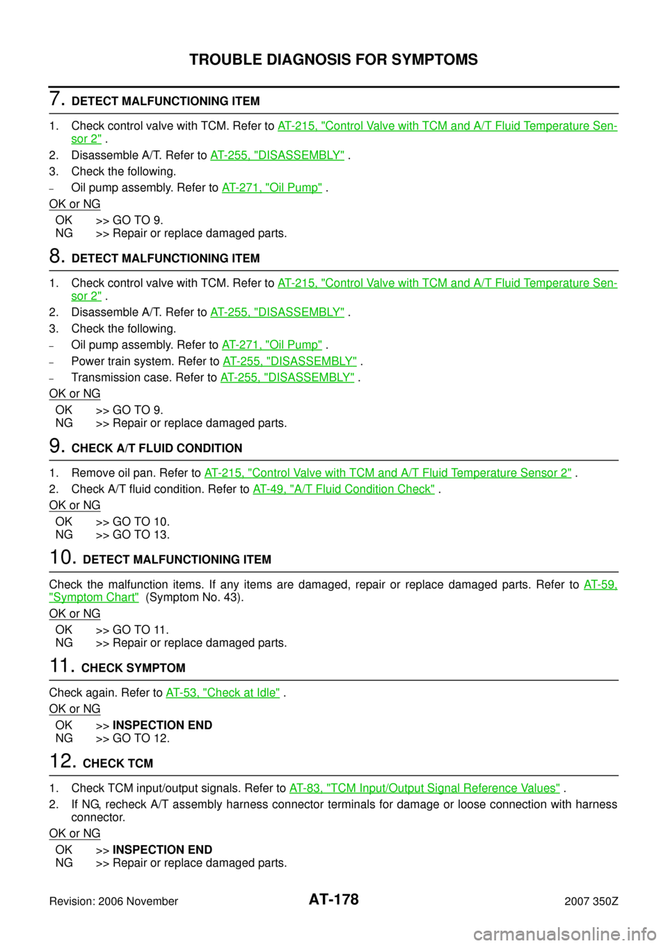
7. DETECT MALFUNCTIONING ITEM
1. Check control valve with TCM. Refer to AT- 2 1 5 , "
Control Valve with TCM and A/T Fluid Temperature Sen-
sor 2" .
2. Disassemble A/T. Refer to AT- 2 5 5 , "
DISASSEMBLY" .
3. Check the following.
–Oil pump assembly. Refer to AT- 2 7 1 , "Oil Pump" .
OK or NG
OK >> GO TO 9.
NG >> Repair or replace damaged parts.
8. DETECT MALFUNCTIONING ITEM
1. Check control valve with TCM. Refer to AT- 2 1 5 , "
Control Valve with TCM and A/T Fluid Temperature Sen-
sor 2" .
2. Disassemble A/T. Refer to AT- 2 5 5 , "
DISASSEMBLY" .
3. Check the following.
–Oil pump assembly. Refer to AT- 2 7 1 , "Oil Pump" .
–Power train system. Refer to AT- 2 5 5 , "DISASSEMBLY" .
–Transmission case. Refer to AT- 2 5 5 , "DISASSEMBLY" .
OK or NG
OK >> GO TO 9.
NG >> Repair or replace damaged parts.
9. CHECK A/T FLUID CONDITION
1. Remove oil pan. Refer to AT- 2 1 5 , "
Control Valve with TCM and A/T Fluid Temperature Sensor 2" .
2. Check A/T fluid condition. Refer to AT- 4 9 , "
A/T Fluid Condition Check" .
OK or NG
OK >> GO TO 10.
NG >> GO TO 13.
10. DETECT MALFUNCTIONING ITEM
Check the malfunction items. If any items are damaged, repair or replace damaged parts. Refer to AT- 5 9 ,
"Symptom Chart" (Symptom No. 43).
OK or NG
OK >> GO TO 11.
NG >> Repair or replace damaged parts.
11 . CHECK SYMPTOM
Check again. Refer to AT- 5 3 , "
Check at Idle" .
OK or NG
OK >>INSPECTION END
NG >> GO TO 12.
12. CHECK TCM
1. Check TCM input/output signals. Refer to AT- 8 3 , "
TCM Input/Output Signal Reference Values" .
2. If NG, recheck A/T assembly harness connector terminals for damage or loose connection with harness
connector.
OK or NG
OK >>INSPECTION END
NG >> Repair or replace damaged parts.
Page 180 of 312
AT-180
TROUBLE DIAGNOSIS FOR SYMPTOMS
Revision: 2006 November2007 350Z
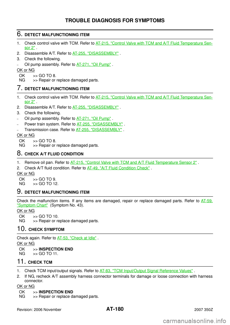
6. DETECT MALFUNCTIONING ITEM
1. Check control valve with TCM. Refer to AT- 2 1 5 , "
Control Valve with TCM and A/T Fluid Temperature Sen-
sor 2" .
2. Disassemble A/T. Refer to AT- 2 5 5 , "
DISASSEMBLY" .
3. Check the following.
–Oil pump assembly. Refer to AT- 2 7 1 , "Oil Pump" .
OK or NG
OK >> GO TO 8.
NG >> Repair or replace damaged parts.
7. DETECT MALFUNCTIONING ITEM
1. Check control valve with TCM. Refer to AT- 2 1 5 , "
Control Valve with TCM and A/T Fluid Temperature Sen-
sor 2" .
2. Disassemble A/T. Refer to AT- 2 5 5 , "
DISASSEMBLY" .
3. Check the following.
–Oil pump assembly. Refer to AT- 2 7 1 , "Oil Pump" .
–Power train system. Refer to AT- 2 5 5 , "DISASSEMBLY" .
–Transmission case. Refer to AT- 2 5 5 , "DISASSEMBLY" .
OK or NG
OK >> GO TO 8.
NG >> Repair or replace damaged parts.
8. CHECK A/T FLUID CONDITION
1. Remove oil pan. Refer to AT- 2 1 5 , "
Control Valve with TCM and A/T Fluid Temperature Sensor 2" .
2. Check A/T fluid condition. Refer to AT- 4 9 , "
A/T Fluid Condition Check" .
OK or NG
OK >> GO TO 9.
NG >> GO TO 12.
9. DETECT MALFUNCTIONING ITEM
Check the malfunction items. If any items are damaged, repair or replace damaged parts. Refer to AT- 5 9 ,
"Symptom Chart" (Symptom No. 43).
OK or NG
OK >> GO TO 10.
NG >> Repair or replace damaged parts.
10. CHECK SYMPTOM
Check again. Refer to AT- 5 3 , "
Check at Idle" .
OK or NG
OK >>INSPECTION END
NG >> GO TO 11.
11 . CHECK TCM
1. Check TCM input/output signals. Refer to AT- 8 3 , "
TCM Input/Output Signal Reference Values" .
2. If NG, recheck A/T assembly harness connector terminals for damage or loose connection with harness
connector.
OK or NG
OK >>INSPECTION END
NG >> Repair or replace damaged parts.