Page 211 of 312

A/T SHIFT LOCK SYSTEM
AT-211
D
E
F
G
H
I
J
K
L
MA
B
AT
Revision: 2006 November2007 350Z
7. DETECT MALFUNCTIONING ITEM
Check the following.
�Harness for short or open between ignition switch and shift lock relay E19 terminal 5.
�Harness for short or open between shift lock relay E19 terminal 3 and A/T device harness connector M47
terminal 1.
�10 A fuse [No. 12, located in the fuse block (J/B)].
�Ignition switch (Refer to PG-4, "POWER SUPPLY ROUTING CIRCUIT" ).
�Shift lock relay.
–Check continuity between shift lock relay E19 terminal 3 and 5.
OK or NG
OK >> GO TO 8.
NG >> Repair or replace damaged parts.
8. CHECK GROUND CIRCUIT
1. Turn ignition switch OFF.
2. Disconnect A/T device harness connector.
3. Check continuity between A/T device harness connector M47
terminal 2 and ground.
If OK, check harness for short to ground and short to power.
OK or NG
OK >> GO TO 9.
NG >> Repair open circuit or short to ground or short to power
in harness or connectors.
9. CHECK SHIFT LOCK SOLENOID AND PARK POSITION SWITCH
1. Connect A/T device harness connector.
2. Turn ignition switch ON.
3. Selector lever is set in “P” position.
4. Check operation.
OK or NG
OK >>INSPECTION END.
NG >> Repair or replace damaged parts.
Condition Continuity
12V direct current supply between terminal 1 and 2 Yes
OFF No
SCIA1245E
Continuity should exist.
SCIA2125E
Condition Brake pedal Operation
When ignition switch is turned to “ON” position and selector lever is set in
“P” position.Depressed Yes
Released No
Page 247 of 312

OVERHAUL
AT-247
D
E
F
G
H
I
J
K
L
MA
B
AT
Revision: 2006 November2007 350Z
1. O-ring 2. Oil pump cover 3. O-ring
4. Oil pump housing 5. Self-sealing bolt 6. Torque converter
7. Converter housing 8. Oil pump housing oil seal 9. Bearing race
10. Needle bearing 11. O-ring 12. Front carrier assembly
13. Needle bearing 14. Snap ring 15. Front sun gear
16. 3rd one-way clutch 17. Snap ring 18. Bearing race
19. Needle bearing 20. Seal ring 21. Input clutch assembly
22. Needle bearing 23. Rear internal gear 24. Brake band
25. Mid carrier assembly 26. Needle bearing 27. Bearing race
28. Rear carrier assembly 29. Needle bearing 30. Mid sun gear
31. Seal ring 32. Rear sun gear 33. 1st one-way clutch
34. Snap ring 35. Needle bearing 36. High and low reverse clutch hub
37. Snap ring 38. Bearing race 39. Needle bearing
Refer to GI section to make sure icons (symbol marks) in the figure. Refer to GI-11, "
Components" .
However, refer to the following for others.
: Apply Genuine RTV silicone sealant or equivalent. Refer to GI-45, "
Recommended Chemical Products and Sealants" .
Page 248 of 312
AT-248
OVERHAUL
Revision: 2006 November2007 350Z
1. Needle bearing 2. Bearing race 3. High and low reverse clutch assembly
4. Needle bearing 5. Direct clutch assembly 6. Reverse brake dish plate
7. Reverse brake dish plate 8. Reverse brake driven plate 9. N-spring
SCIA8377E
Page 249 of 312
OVERHAUL
AT-249
D
E
F
G
H
I
J
K
L
MA
B
AT
Revision: 2006 November2007 350Z
10. Reverse brake drive plate 11. Reverse brake retaining plate 12. Snap ring
13. D-ring 14. D-ring 15. Reverse brake piston
16. Return spring 17. Spring retainer 18. Snap ring
Refer to GI section to make sure icons (symbol marks) in the figure. Refer to GI-11, "
Components" .
Page 258 of 312
AT-258
DISASSEMBLY
Revision: 2006 November2007 350Z
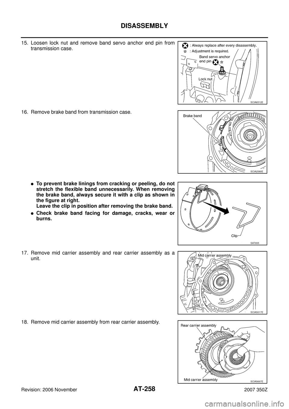
15. Loosen lock nut and remove band servo anchor end pin from
transmission case.
16. Remove brake band from transmission case.
�To prevent brake linings from cracking or peeling, do not
stretch the flexible band unnecessarily. When removing
the brake band, always secure it with a clip as shown in
the figure at right.
Leave the clip in position after removing the brake band.
�Check brake band facing for damage, cracks, wear or
burns.
17. Remove mid carrier assembly and rear carrier assembly as a
unit.
18. Remove mid carrier assembly from rear carrier assembly.
SCIA6512E
SCIA2580E
SAT655
SCIA5017E
SCIA5697E
Page 260 of 312
AT-260
DISASSEMBLY
Revision: 2006 November2007 350Z
24. Remove high and low reverse clutch assembly from direct clutch
assembly.
CAUTION:
Make sure that needle bearing is installed to high and low
reverse clutch assembly edge surface.
25. Remove direct clutch assembly from reverse brake.
26. Remove needle bearing from drum support.
27. Remove snap ring from A/T assembly harness connector.
28. Push A/T assembly harness connector.
CAUTION:
Be careful not to damage connector.
SCIA2306E
SCIA5019E
SCIA5198E
SCIA5021E
SCIA5022E
Page 265 of 312
DISASSEMBLY
AT-265
D
E
F
G
H
I
J
K
L
MA
B
AT
Revision: 2006 November2007 350Z
50. Remove seal rings from output shaft.
51. Remove needle bearing from transmission case.
52. Remove revolution sensor from transmission case.
CAUTION:
�Do not subject it to impact by dropping or hitting it.
�Do not disassemble.
�Do not allow metal filings, etc. to get on the sensor's front
edge magnetic area.
�Do not place in an area affected by magnetism.
53. Remove reverse brake snap ring (fixing plate) using 2 flat-
bladed screwdrivers.
NOTE:
Press out snap ring from transmission case oil pan side gap
using a flat-bladed screwdriver, and remove it using another
screwdriver.
54. Remove reverse brake retaining plate from transmission case.
�Check facing for burns, cracks or damage. If necessary,
replace the plate.
55. Remove N-spring from transmission case.
SCIA5209E
SCIA5031E
SCIA2320E
SCIA5032E
SCIA5214E
Page 266 of 312
AT-266
DISASSEMBLY
Revision: 2006 November2007 350Z
56. Remove reverse brake drive plates, driven plates and dish
plates from transmission case.
CAUTION:
Be careful to remove it with N-spring.
57. Remove snap ring (fixing spring retainer) using a flat-bladed
screwdriver.
58. Remove spring retainer and return spring from transmission
case.
59. Remove seal rings from drum support.
60. Remove needle bearing from drum support edge surface.
SCIA2322E
SCIA2323E
SCIA2324E
SCIA3333E
SCIA2796E