Page 267 of 312
DISASSEMBLY
AT-267
D
E
F
G
H
I
J
K
L
MA
B
AT
Revision: 2006 November2007 350Z
61. Remove reverse brake piston from transmission case with com-
pressed air. Refer to AT- 2 5 2 , "
Oil Channel" .
CAUTION:
Care should be taken not to abruptly blow air. It makes pis-
tons incline, as the result, it becomes hard to disassemble
the pistons.
62. Remove D-rings from reverse brake piston.
63. Use a pin punch [4 mm (0.16 in) dia. commercial service tool] to
knock out retaining pin.
64. Remove manual shaft retaining pin using pair of nippers.
SCIA5047E
SCIA6330E
SCIA2328E
SCIA2329E
Page 292 of 312
AT-292
ASSEMBLY
Revision: 2006 November2007 350Z
9. Install return spring to servo assembly.
10. Install servo assembly in transmission case.
11. Install snap ring to transmission case using pair of snap ring pli-
ers.
12. Install D-rings in reverse brake piston.
CAUTION:
�Do not reuse D-rings.
�Apply ATF to D-rings.
13. Install reverse brake piston in transmission case.
SCIA5717E
SCIA5679E
SCIA2333E
SCIA6330E
SCIA2325E
Page 294 of 312
AT-294
ASSEMBLY
Revision: 2006 November2007 350Z
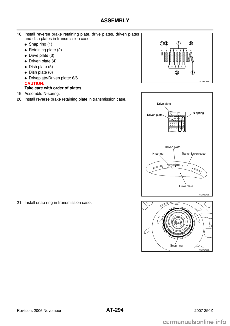
18. Install reverse brake retaining plate, drive plates, driven plates
and dish plates in transmission case.
�Snap ring (1)
�Retaining plate (2)
�Drive plate (3)
�Driven plate (4)
�Dish plate (5)
�Dish plate (6)
�Driveplate/Driven plate: 6/6
CAUTION:
Take care with order of plates.
19. Assemble N-spring.
20. Install reverse brake retaining plate in transmission case.
21. Install snap ring in transmission case.SCIA8088E
SCIA5249E
SCIA2439E
Page 295 of 312

ASSEMBLY
AT-295
D
E
F
G
H
I
J
K
L
MA
B
AT
Revision: 2006 November2007 350Z
22. Measure clearance between retaining plate and snap ring. If not
within specified clearance, select proper retaining plate. Refer to
“Parts Information” for retaining plate selection.
23. Install needle bearing to transmission case.
CAUTION:
�Take care with the direction of needle bearing. Refer to
AT- 2 5 3 , "
Locations of Adjusting Shims, Needle Bearings,
Thrust Washers and Snap Rings" .
�Apply petroleum jelly to needle bearing.
24. Install revolution sensor to transmission case, and then tighten
mounting bolt to the specified torque. Refer to AT- 2 4 6 , "
Compo-
nents" .
CAUTION:
�Do not subject it to impact by dropping or hitting it.
�Do not disassemble.
�Do not allow metal filings, etc. to get on the sensor's front
edge magnetic area.
�Do not place in an area affected by magnetism.
25. As shown in the figure, drive rear oil seal into rear extension until
it is flush using a drift.
CAUTION:
�Do not reuse rear oil seal.
�Apply ATF to rear oil seal.
26. Install return spring (1) to parking pawl (2).Specified clearance “A”:
Refer to AT- 3 1 2 , "
Reverse Brake" .
SCIA3129E
SCIA5031E
SCIA2320E
SCIA5311E
SCIA6180J
Page 298 of 312
AT-298
ASSEMBLY
Revision: 2006 November2007 350Z
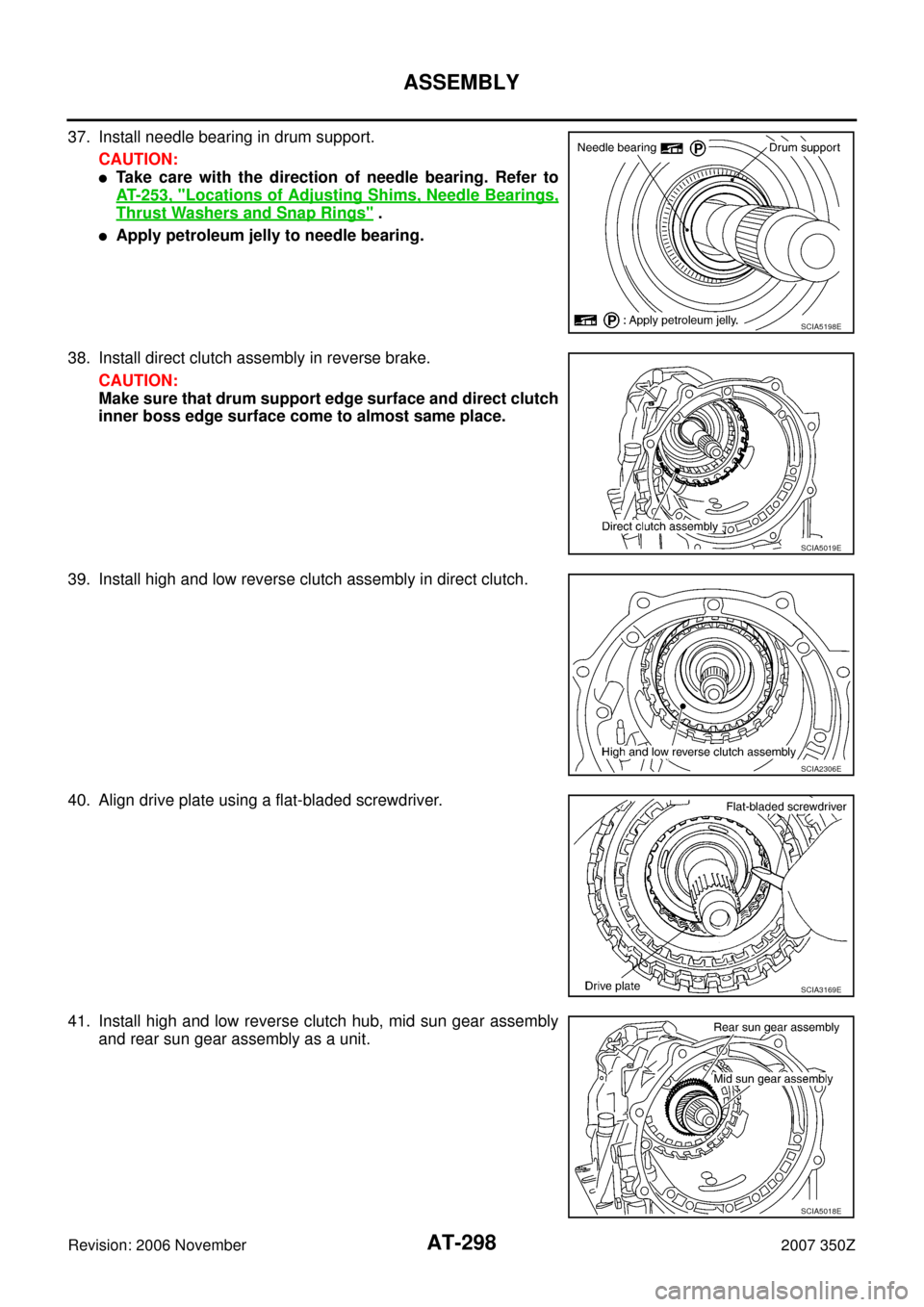
37. Install needle bearing in drum support.
CAUTION:
�Take care with the direction of needle bearing. Refer to
AT- 2 5 3 , "
Locations of Adjusting Shims, Needle Bearings,
Thrust Washers and Snap Rings" .
�Apply petroleum jelly to needle bearing.
38. Install direct clutch assembly in reverse brake.
CAUTION:
Make sure that drum support edge surface and direct clutch
inner boss edge surface come to almost same place.
39. Install high and low reverse clutch assembly in direct clutch.
40. Align drive plate using a flat-bladed screwdriver.
41. Install high and low reverse clutch hub, mid sun gear assembly
and rear sun gear assembly as a unit.
SCIA5198E
SCIA5019E
SCIA2306E
SCIA3169E
SCIA5018E
Page 301 of 312
ASSEMBLY
AT-301
D
E
F
G
H
I
J
K
L
MA
B
AT
Revision: 2006 November2007 350Z
50. Install band servo anchor end pin and lock nut in transmission
case.
CAUTION:
Do not reuse band servo anchor end pin.
51. Install brake band in transmission case.
CAUTION:
Assemble it so that identification to avoid incorrect installa-
tion faces servo side.
52. Install front sun gear to front carrier assembly.
CAUTION:
Apply ATF to front sun gear bearing and 3rd one-way clutch
end bearing.
53. Install needle bearing to front sun gear.
CAUTION:
�Take care with the direction of needle bearing. Refer to
AT- 2 5 3 , "
Locations of Adjusting Shims, Needle Bearings,
Thrust Washers and Snap Rings" .
�Apply petroleum jelly to needle bearing.
54. Adjust brake band tilting using a clip so that brake band contacts
front sun gear drum evenly.
SCIA6512E
SCIA5498E
SCIA5014E
SCIA2808E
SCIA5033E
Page 302 of 312
AT-302
ASSEMBLY
Revision: 2006 November2007 350Z
55. Adjust brake band.
a. Loosen lock nut.
b. Tighten band servo anchor end pin to the specified torque.
c. Back of band servo anchor end pin three turns.
d. Holding band servo anchor end pin, tighten lock nut to the spec-
ified torque. Refer to AT- 2 4 6 , "
Components" .
AdjustmentNCS0009J
TOTAL END PLAY
�Measure clearance between front sun gear and bearing race for
oil pump cover.
�Select proper thickness of bearing race so that end play is within
specifications.
1. Measure dimensions “K” and “L” and then calculate dimension
“J”.
a. Measure dimension “K”.: 5.0 N·m (0.51 kg-m, 44 in-lb)
SCIA5498E
SCIA2810E
SCIA7073E
SCIA7074E
Page 306 of 312
AT-306
ASSEMBLY
Revision: 2006 November2007 350Z
8. Make sure that brake band does not close turbine revolution
sensor hole.
9. Install control valve with TCM.
a. Connect TCM connector and park/neutral position switch con-
nector.
b. Install A/T assembly harness connector from control valve with
TCM.
c. Connect TCM connectors.
d. Install O-ring to A/T assembly harness connector.
CAUTION:
�Do not reuse O-ring.
�Apply ATF to O-ring.
SCIA5034E
SCIA5449E
SCIA5450E
SCIA5447E
SCIA5155E