Page 55 of 142
TROUBLE DIAGNOSIS
ATC-55
C
D
E
F
G
H
I
K
L
MA
B
AT C
Revision: 2006 November2007 350Z
Potentio Temperature Control (PTC)
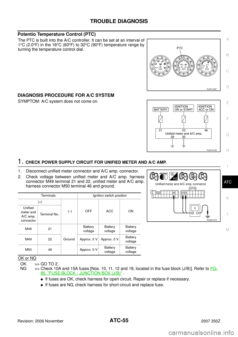
The PTC is built into the A/C controller. It can be set at an interval of
1°C (2.0°F) in the 18°C (60°F) to 32°C (90°F) temperature range by
turning the temperature control dial.
DIAGNOSIS PROCEDURE FOR A/C SYSTEM
SYMPTOM: A/C system does not come on.
1. CHECK POWER SUPPLY CIRCUIT FOR UNIFIED METER AND A/C AMP.
1. Disconnect unified meter connector and A/C amp. connector.
2. Check voltage between unified meter and A/C amp. harness
connector M49 terminal 21 and 22, unified meter and A/C amp.
harness connector M50 terminal 46 and ground.
OK or NG
OK >> GO TO 2.
NG >> Check 10A and 15A fuses [Nos. 10, 11, 12 and 19, located in the fuse block (J/B)]. Refer to PG-
85, "FUSE BLOCK - JUNCTION BOX (J/B)" .
�If fuses are OK, check harness for open circuit. Repair or replace if necessary.
�If fuses are NG, check harness for short circuit and replace fuse.
SJIA1124E
RJIA1374E
Terminals Ignition switch position
(+)
(−)OFF ACC ON Unified
meter and
A/C amp.
connectorTerminal No.
M49 21
GroundBattery
voltageBattery
voltageBattery
voltage
M49 22 Approx. 0 V Approx. 0 VBattery
voltage
M50 46 Approx. 0 VBattery
voltageBattery
voltage
RJIA2121E
Page 56 of 142
ATC-56
TROUBLE DIAGNOSIS
Revision: 2006 November2007 350Z
2. CHECK GROUND CIRCUIT FOR UNIFIED METER AND A/C AMP.
1. Turn ignition switch OFF.
2. Check continuity between unified meter and A/C amp. harness
connector M49 terminal 29, 30 and ground.
OK or NG
OK >> Replace unified meter and A/C amp.
NG >> Repair harness or connector.
LAN System CircuitNJS0000Z
SYMPTOM: Mode door motor, intake door motor and/or air mix door motor does not operate normally.
DIAGNOSIS PROCEDURE FOR LAN CIRCUIT
1. CHECK POWER SUPPLY FOR UNIFIED METER AND A/C AMP.
1. Turn ignition switch ON.
2. Check voltage between unified meter and A/C amp. harness
connector M50 terminal 54 and ground.
OK or NG
OK >> GO TO 2.
NG >> Replace unified meter and A/C amp.29, 30 – Ground : Continuity should exist.
RJIA1985E
RJIA2122E
54 – Ground : Battery voltage
RJIA1986E
Page 58 of 142
ATC-58
TROUBLE DIAGNOSIS
Revision: 2006 November2007 350Z
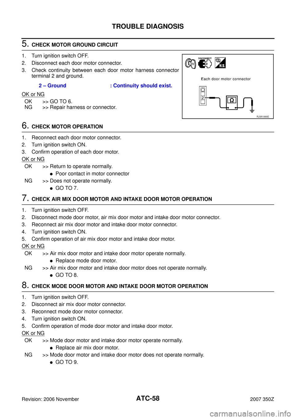
5. CHECK MOTOR GROUND CIRCUIT
1. Turn ignition switch OFF.
2. Disconnect each door motor connector.
3. Check continuity between each door motor harness connector
terminal 2 and ground.
OK or NG
OK >> GO TO 6.
NG >> Repair harness or connector.
6. CHECK MOTOR OPERATION
1. Reconnect each door motor connector.
2. Turn ignition switch ON.
3. Confirm operation of each door motor.
OK or NG
OK >> Return to operate normally.
�Poor contact in motor connector
NG >> Does not operate normally.
�GO TO 7.
7. CHECK AIR MIX DOOR MOTOR AND INTAKE DOOR MOTOR OPERATION
1. Turn ignition switch OFF.
2. Disconnect mode door motor, air mix door motor and intake door motor connector.
3. Reconnect air mix door motor and intake door motor connector.
4. Turn ignition switch ON.
5. Confirm operation of air mix door motor and intake door motor.
OK or NG
OK >> Air mix door motor and intake door motor operate normally.
�Replace mode door motor.
NG >> Air mix door motor and intake door motor does not operate normally.
�GO TO 8.
8. CHECK MODE DOOR MOTOR AND INTAKE DOOR MOTOR OPERATION
1. Turn ignition switch OFF.
2. Disconnect air mix door motor connector.
3. Reconnect mode door motor connector.
4. Turn ignition switch ON.
5. Confirm operation of mode door motor and intake door motor.
OK or NG
OK >> Mode door motor and intake door motor operate normally.
�Replace air mix door motor.
NG >> Mode door motor and intake door motor does not operate normally.
�GO TO 9. 2 – Ground : Continuity should exist.
RJIA1990E
Page 59 of 142
TROUBLE DIAGNOSIS
ATC-59
C
D
E
F
G
H
I
K
L
MA
B
AT C
Revision: 2006 November2007 350Z
9. CHECK MODE DOOR MOTOR AND AIR MIX DOOR MOTOR OPERATION
1. Turn ignition switch OFF.
2. Disconnect intake door motor connector.
3. Reconnect air mix door motor connector.
4. Turn ignition switch ON.
5. Confirm operation of mode door motor and air mix door motor.
OK or NG
OK >> Mode door motor and air mix door motor operate normally.
�Replace intake door motor.
NG >> Mode door motor and air mix door motor does not operate normally.
�Replace unified meter and A/C amp.
Page 72 of 142
ATC-72
TROUBLE DIAGNOSIS
Revision: 2006 November2007 350Z
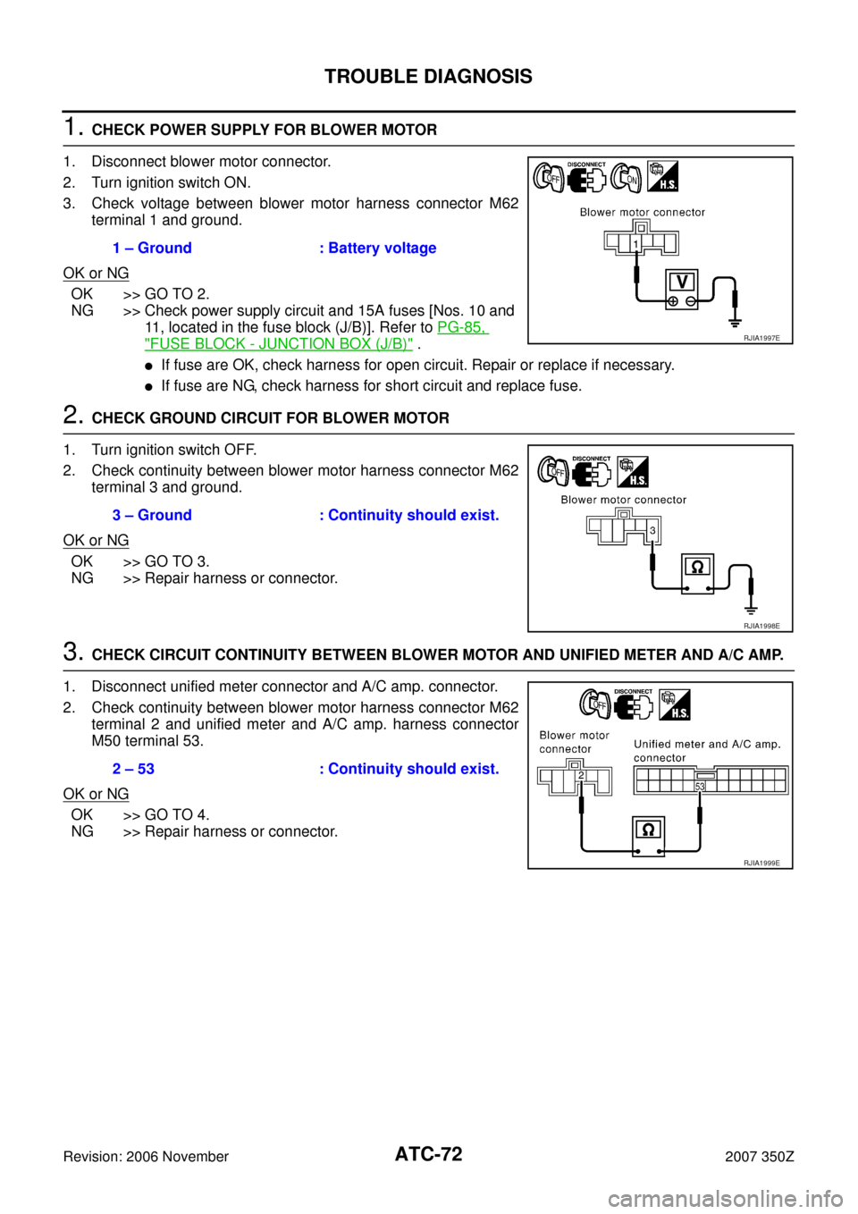
1. CHECK POWER SUPPLY FOR BLOWER MOTOR
1. Disconnect blower motor connector.
2. Turn ignition switch ON.
3. Check voltage between blower motor harness connector M62
terminal 1 and ground.
OK or NG
OK >> GO TO 2.
NG >> Check power supply circuit and 15A fuses [Nos. 10 and
11, located in the fuse block (J/B)]. Refer to PG-85,
"FUSE BLOCK - JUNCTION BOX (J/B)" .
�If fuse are OK, check harness for open circuit. Repair or replace if necessary.
�If fuse are NG, check harness for short circuit and replace fuse.
2. CHECK GROUND CIRCUIT FOR BLOWER MOTOR
1. Turn ignition switch OFF.
2. Check continuity between blower motor harness connector M62
terminal 3 and ground.
OK or NG
OK >> GO TO 3.
NG >> Repair harness or connector.
3. CHECK CIRCUIT CONTINUITY BETWEEN BLOWER MOTOR AND UNIFIED METER AND A/C AMP.
1. Disconnect unified meter connector and A/C amp. connector.
2. Check continuity between blower motor harness connector M62
terminal 2 and unified meter and A/C amp. harness connector
M50 terminal 53.
OK or NG
OK >> GO TO 4.
NG >> Repair harness or connector.1 – Ground : Battery voltage
RJIA1997E
3 – Ground : Continuity should exist.
RJIA1998E
2 – 53 : Continuity should exist.
RJIA1999E
Page 73 of 142
TROUBLE DIAGNOSIS
ATC-73
C
D
E
F
G
H
I
K
L
MA
B
AT C
Revision: 2006 November2007 350Z
4. CHECK UNIFIED METER AND A/C AMP. OUTPUT SIGNAL
1. Reconnect blower motor connector and unified meter and A/C
amp. connector.
2. Turn ignition switch ON.
3. Change the fan speed from Lo to Hi, and check the duty ratios
between blower motor harness connector M62 terminal 2 and
ground by using an oscilloscope. Normal terminal 2 drive signal
duty ratios are shown in the table below.
OK or NG
OK >> Replace blower motor after confirming the fan air flow does not change.
NG >> Replace unified meter and A/C amp.
COMPONENT INSPECTION
Blower Motor
Confirm smooth rotation of the blower motor.
�Ensure that there are no foreign particles inside the blower unit.
RJIA2000E
RJIA1390E
RJIA0905E
Page 76 of 142
ATC-76
TROUBLE DIAGNOSIS
Revision: 2006 November2007 350Z
1. CHECK AMBIENT SENSOR CIRCUIT AND INTAKE SENSOR CIRCUIT
Check ambient sensor and intake sensor. Refer to AT C - 4 6 , "
FUNCTION CONFIRMATION PROCEDURE" ,
see No. 9.
OK or NG
OK >> GO TO 2.
NG >>
�Malfunctioning ambient sensor: Refer to AT C - 9 2 , "Ambient Sensor Circuit" .
�Malfunctioning intake sensor: Refer to ATC-100, "Intake Sensor Circuit" .
2. PERFORM AUTO ACTIVE TEST
Refer to PG-20, "
Auto Active Test" .
Dose the magnet clutch operate?
YES >>� WITH CONSULT-III: GO TO 5.
� WITHOUT CONSULT-III: GO TO 6.
NO >> Check 10A fuse (No. 79, located in IPDM E/R), and GO TO 3. Refer to PG-23, "
IPDM E/R Termi-
nal Arrangement" .
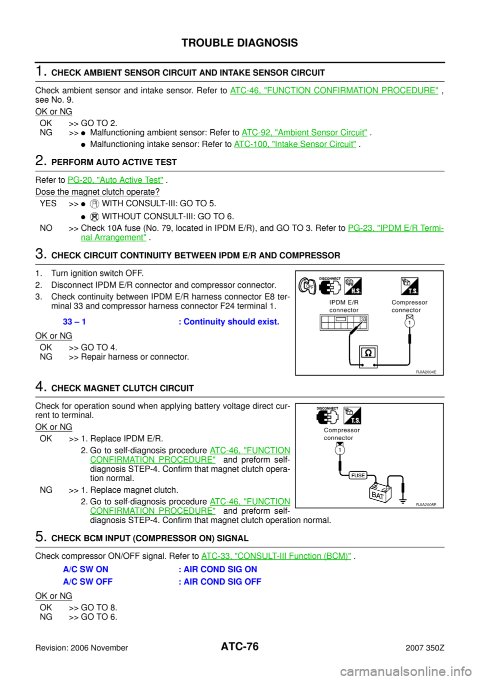
3. CHECK CIRCUIT CONTINUITY BETWEEN IPDM E/R AND COMPRESSOR
1. Turn ignition switch OFF.
2. Disconnect IPDM E/R connector and compressor connector.
3. Check continuity between IPDM E/R harness connector E8 ter-
minal 33 and compressor harness connector F24 terminal 1.
OK or NG
OK >> GO TO 4.
NG >> Repair harness or connector.
4. CHECK MAGNET CLUTCH CIRCUIT
Check for operation sound when applying battery voltage direct cur-
rent to terminal.
OK or NG
OK >> 1. Replace IPDM E/R.
2. Go to self-diagnosis procedure AT C - 4 6 , "
FUNCTION
CONFIRMATION PROCEDURE" and preform self-
diagnosis STEP-4. Confirm that magnet clutch opera-
tion normal.
NG >> 1. Replace magnet clutch.
2. Go to self-diagnosis procedure AT C - 4 6 , "
FUNCTION
CONFIRMATION PROCEDURE" and preform self-
diagnosis STEP-4. Confirm that magnet clutch operation normal.
5. CHECK BCM INPUT (COMPRESSOR ON) SIGNAL
Check compressor ON/OFF signal. Refer to AT C - 3 3 , "
CONSULT-III Function (BCM)" .
OK or NG
OK >> GO TO 8.
NG >> GO TO 6.
33 – 1 : Continuity should exist.
RJIA2004E
RJIA2005E
A/C SW ON : AIR COND SIG ON
A/C SW OFF : AIR COND SIG OFF
Page 77 of 142
TROUBLE DIAGNOSIS
ATC-77
C
D
E
F
G
H
I
K
L
MA
B
AT C
Revision: 2006 November2007 350Z
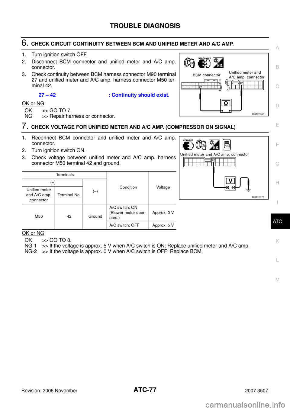
6. CHECK CIRCUIT CONTINUITY BETWEEN BCM AND UNIFIED METER AND A/C AMP.
1. Turn ignition switch OFF.
2. Disconnect BCM connector and unified meter and A/C amp.
connector.
3. Check continuity between BCM harness connector M90 terminal
27 and unified meter and A/C amp. harness connector M50 ter-
minal 42.
OK or NG
OK >> GO TO 7.
NG >> Repair harness or connector.
7. CHECK VOLTAGE FOR UNIFIED METER AND A/C AMP. (COMPRESSOR ON SIGNAL)
1. Reconnect BCM connector and unified meter and A/C amp.
connector.
2. Turn ignition switch ON.
3. Check voltage between unified meter and A/C amp. harness
connector M50 terminal 42 and ground.
OK or NG
OK >> GO TO 8.
NG-1 >> If the voltage is approx. 5 V when A/C switch is ON: Replace unified meter and A/C amp.
NG-2 >> If the voltage is approx. 0 V when A/C switch is OFF: Replace BCM.27 – 42 : Continuity should exist.
RJIA2006E
Terminals
Condition Voltage (+)
(−) Unified meter
and A/C amp.
connectorTerminal No.
M50 42 GroundA/C switch: ON
(Blower motor oper-
ates.)Approx. 0 V
A/C switch: OFF Approx. 5 V
RJIA2007E