Page 100 of 142

ATC-100
TROUBLE DIAGNOSIS
Revision: 2006 November2007 350Z
Intake Sensor CircuitNJS0001D
COMPONENT DESCRIPTION
Intake Sensor
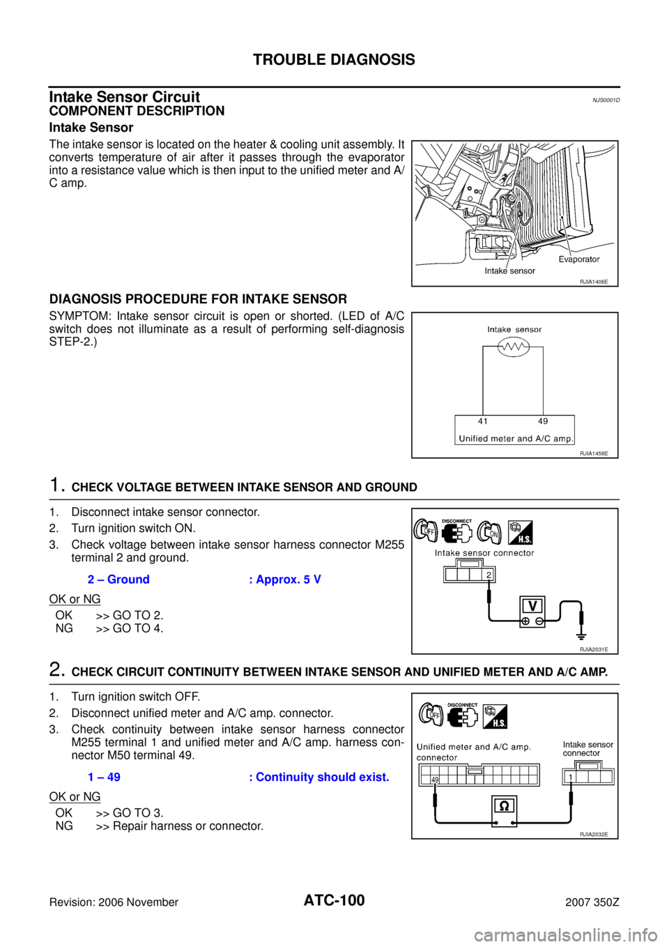
The intake sensor is located on the heater & cooling unit assembly. It
converts temperature of air after it passes through the evaporator
into a resistance value which is then input to the unified meter and A/
C amp.
DIAGNOSIS PROCEDURE FOR INTAKE SENSOR
SYMPTOM: Intake sensor circuit is open or shorted. (LED of A/C
switch does not illuminate as a result of performing self-diagnosis
STEP-2.)
1. CHECK VOLTAGE BETWEEN INTAKE SENSOR AND GROUND
1. Disconnect intake sensor connector.
2. Turn ignition switch ON.
3. Check voltage between intake sensor harness connector M255
terminal 2 and ground.
OK or NG
OK >> GO TO 2.
NG >> GO TO 4.
2. CHECK CIRCUIT CONTINUITY BETWEEN INTAKE SENSOR AND UNIFIED METER AND A/C AMP.
1. Turn ignition switch OFF.
2. Disconnect unified meter and A/C amp. connector.
3. Check continuity between intake sensor harness connector
M255 terminal 1 and unified meter and A/C amp. harness con-
nector M50 terminal 49.
OK or NG
OK >> GO TO 3.
NG >> Repair harness or connector.
RJIA1406E
RJIA1458E
2 – Ground : Approx. 5 V
RJIA2031E
1 – 49 : Continuity should exist.
RJIA2032E
Page 101 of 142

TROUBLE DIAGNOSIS
ATC-101
C
D
E
F
G
H
I
K
L
MA
B
AT C
Revision: 2006 November2007 350Z
3. CHECK INTAKE SENSOR
Refer to ATC-101, "
Intake Sensor" .
OK or NG
OK >> 1. Replace unified meter and A/C amp.
2. Go to self-diagnosis AT C - 4 6 , "
FUNCTION CONFIRMATION PROCEDURE" and perform self-
diagnosis STEP-2.
NG >> 1. Replace intake sensor.
2. Go to self-diagnosis AT C - 4 6 , "
FUNCTION CONFIRMATION PROCEDURE" and perform self-
diagnosis STEP-2.
4. CHECK CIRCUIT CONTINUITY BETWEEN INTAKE SENSOR AND UNIFIED METER AND A/C AMP.
1. Turn ignition switch OFF.
2. Disconnect unified meter and A/C amp. connector.
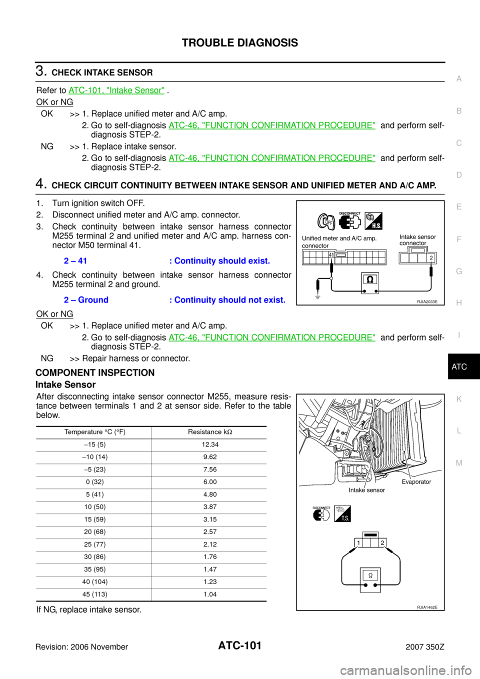
3. Check continuity between intake sensor harness connector
M255 terminal 2 and unified meter and A/C amp. harness con-
nector M50 terminal 41.
4. Check continuity between intake sensor harness connector
M255 terminal 2 and ground.
OK or NG
OK >> 1. Replace unified meter and A/C amp.
2. Go to self-diagnosis AT C - 4 6 , "
FUNCTION CONFIRMATION PROCEDURE" and perform self-
diagnosis STEP-2.
NG >> Repair harness or connector.
COMPONENT INSPECTION
Intake Sensor
After disconnecting intake sensor connector M255, measure resis-
tance between terminals 1 and 2 at sensor side. Refer to the table
below.
If NG, replace intake sensor.2 – 41 : Continuity should exist.
2 – Ground : Continuity should not exist.
RJIA2033E
Temperature °C (°F) Resistance kΩ
−15 (5) 12.34
−10 (14) 9.62
−5 (23) 7.56
0 (32) 6.00
5 (41) 4.80
10 (50) 3.87
15 (59) 3.15
20 (68) 2.57
25 (77) 2.12
30 (86) 1.76
35 (95) 1.47
40 (104) 1.23
45 (113) 1.04
RJIA1462E
Page 142 of 142
ATC-142
SERVICE DATA AND SPECIFICATIONS (SDS)
Revision: 2006 November2007 350Z
SERVICE DATA AND SPECIFICATIONS (SDS)PFP:00030
CompressorNJS0002B
LubricantNJS0002C
RefrigerantNJS0002D
Engine Idling SpeedNJS0002E
Refer to EC-718, "Idle Speed and Ignition Timing" .
Belt TensionNJS0002F
Refer to EM-12, "DRIVE BELTS" .
ModelVALEO THERMAL SYSTEMS JAPAN make
DCS-17IC
Ty p eVariable displacement swash plate
Displacement
cm
3 (cu in)/revMax. 171 (10.4)
Cylinder bore × stroke
mm (in)32 (1.26) × 30.5 (1.20)
Direction of rotationClockwise (viewed from drive end)
Drive beltPoly V
ModelVALEO THERMAL SYSTEMS JAPAN make
DCS-17IC
NameNissan A/C System Oil Type S (DH-PS)
Capacity
m (US fl oz, lmp fl oz)Total in system 150 (5.07, 5.3)
Compressor (Service part) charging amount 150 (5.07, 5.3)
Ty p eHFC-134a (R-134a)
Capacity
kg (lb)0.55 (1.21)