Page 46 of 116

AV-46
AUDIO
Revision: 2006 November2007 350Z
Removal and Installation of Audio Unit (Base system)NKS002BH
REMOVAL
1. Remove cluster lid C. Refer to IP-10, "INSTRUMENT PANEL ASSEMBLY" .
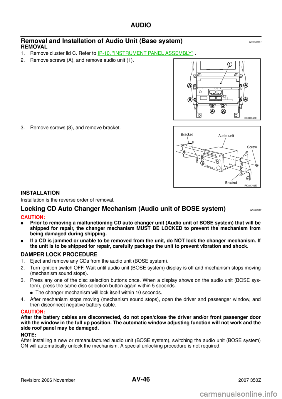
2. Remove screws (A), and remove audio unit (1).
3. Remove screws (8), and remove bracket.
INSTALLATION
Installation is the reverse order of removal.
Locking CD Auto Changer Mechanism (Audio unit of BOSE system)NKS002BI
CAUTION:
�Prior to removing a malfunctioning CD auto changer unit (Audio unit of BOSE system) that will be
shipped for repair, the changer mechanism MUST BE LOCKED to prevent the mechanism from
being damaged during shipping.
�If a CD is jammed or unable to be removed from the unit, do NOT lock the changer mechanism. If
the unit is to be shipped for repair, carefully package the unit to prevent vibration and shock.
DAMPER LOCK PROCEDURE
1. Eject and remove any CDs from the audio unit (BOSE system).
2. Turn ignition switch OFF. Wait until audio unit (BOSE system) display is off and mechanism stops moving
(mechanism sound stops).
3. Press any one of the disc selection buttons once. When a display shows on the audio unit (BOSE sys-
tem), press the same disc selection button again within 5 seconds.
�The changer mechanism will lock itself within 10 seconds.
4. After mechanism stops moving (mechanism sound stops), open the driver and passenger window, and
then disconnect negative battery cable.
CAUTION:
After the battery cables are disconnected, do not open/close the driver and/or front passenger door
with the window in the full up position. The automatic window adjusting function will not work and the
side roof panel may be damaged.
NOTE:
After installing a new or remanufactured audio unit (BOSE system), switching the audio unit (BOSE system)
ON will automatically unlock the mechanism. A special unlocking procedure is not required.
SKIB7343E
PKIA1765E
Page 69 of 116

NAVIGATION SYSTEM
AV-69
C
D
E
F
G
H
I
J
L
MA
B
AV
Revision: 2006 November2007 350Z
Terminals and Reference Value for NAVI Control UnitNKS000D3
Terminal
(Wire color)
ItemSignal
input/
outputCondition
Reference value
(+) (–)Ignition
switchOperation
1 (B) Ground Ground — ON — Approx. 0 V
2 (Y) Ground Battery power supply Input OFF — Battery voltage
5 (LG) Ground ACC power supply Input ACC — Battery voltage
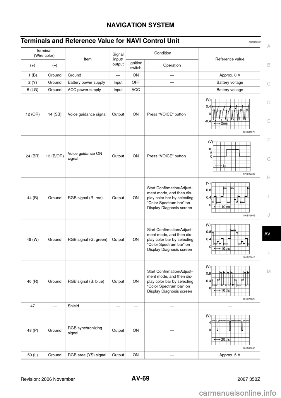
12 (OR) 14 (SB) Voice guidance signal Output ON Press “VOICE” button
24 (BR) 13 (B/OR)Voice guidance ON
signalOutput ON Press “VOICE” button
44 (B) Ground RGB signal (R: red) Output ONStart Confirmation/Adjust-
ment mode, and then dis-
play color bar by selecting
“Color Spectrum bar” on
Display Diagnosis screen
45 (W) Ground RGB signal (G: green) Output ONStart Confirmation/Adjust-
ment mode, and then dis-
play color bar by selecting
“Color Spectrum bar” on
Display Diagnosis screen
46 (R) Ground RGB signal (B: blue) Output ONStart Confirmation/Adjust-
ment mode, and then dis-
play color bar by selecting
“Color Spectrum bar” on
Display Diagnosis screen
47 — Shield — — — —
48 (P) GroundRGB synchronizing
signalOutput ON —
50 (L) Ground RGB area (YS) signal Output ON — Approx. 5 V
SKIB3597E
SKIB0232E
SKIB7360E
SKIB7361E
SKIB7362E
SKIB3603E
Page 70 of 116
AV-70
NAVIGATION SYSTEM
Revision: 2006 November2007 350Z
61 (PU) Ground Illumination signal Input ONLighting switch ON Approx. 12 V
Lighting switch OFF Approx. 0 V
63 (SB) Ground Ignition signal Input ON — Battery voltage
65 (GY) Ground Reverse signal Input ONSelect R position Approx. 12 V
Other position Approx. 0 V
66 (L/B) GroundVehicle speed signal
(2-pulse)Input ONWhen vehicle speed is
approx. 40 km/h (25 MPH)
68 — Shield — — — —
69 (G) GroundCommunication
signal (+)Input/
OutputONOperate navigation system
with NAVI switch
70 (R) GroundCommunication
signal (–)Input/
OutputONOperate navigation system
with NAVI switch
73 (GY) Ground GPS signal Input ON Connector is not connected Approx. 5 VTe r m i n a l
(Wire color)
ItemSignal
input/
outputCondition
Reference value
(+) (–)Ignition
switchOperation
SKIA6649J
SKIB7378E
SKIB7379E
Page 72 of 116
AV-72
NAVIGATION SYSTEM
Revision: 2006 November2007 350Z
15 (L) GroundCommunication
signal (–)Input/
OutputONOperate navigation system
with NAVI switch
16 (R) GroundCommunication
signal (+)Input/
OutputONOperate navigation system
with NAVI switch
19 (LG) Ground ACC power supply Input ACC — Battery voltage
21 (Y) Ground Battery power supply Input OFF — Battery voltage
22 (B) Ground Ground — ON — Approx. 0 V
23 (Y) Ground Battery power supply Input OFF — Battery voltage
24 (B) Ground Ground — ON — Approx. 0 VTerminal
(Wire color)
ItemSignal
input/
outputCondition
Reference value
(+) (–)Ignition
switchOperation
SKIB7379E
SKIB7378E
Page 73 of 116
NAVIGATION SYSTEM
AV-73
C
D
E
F
G
H
I
J
L
MA
B
AV
Revision: 2006 November2007 350Z
Terminals and Reference Value for NAVI SwitchNKS000D5
Terminal
(Wire color)
ItemSignal
input/
outputCondition
Reference value
(+) (–)Ignition
switchOperation
1 (LG) Ground ACC power supply Input ACC — Battery voltage
2 (R/L) Ground Illumination signal Input ONLighting switch ON Approx. 12 V
Lighting switch OFF Approx. 0 V
3 (R/Y) GroundIllumination control
signalInput ONIllumination control switch is
operated by lighting switch
in ON positionChanges between approx. 0 and
approx. 12 V
4 (R) GroundCommunication
signal (+)Input/
OutputONOperate navigation system
with NAVI switch
5 (L) GroundCommunication
signal (–)Input/
OutputONOperate navigation system
with NAVI switch
7 (B) Ground Ground — ON — Approx. 0 V
SKIB7378E
SKIB7379E
Page 84 of 116
AV-84
NAVIGATION SYSTEM
Revision: 2006 November2007 350Z
All Images Are Not DisplayedNKS000DI
Symptom: RGB image such as a map screen is not displayed.
1. CHECK CONDITION
Check if brightness of screen changes when button on NAVI switch is turned on after turning on ignition
switch.
Does brightness of screen change?
YES >> GO TO 5.
NO >> GO TO 2.
2. CHECK NAVI CONTROL UNIT POWER SUPPLY AND GROUND CIRCUIT
1. Check voltage between NAVI control unit harness connector ter-
minals and ground.
2. Turn ignition switch OFF.
3. Disconnect NAVI control unit connector.
4. Check continuity between NAVI control unit harness connector
B104 terminal 1 and ground.
OK or NG
OK >> GO TO 3.
NG >> Repair harness or connector.
Terminals
OFF ACC ON (+)
(–)
Connector Terminal
B1042
GroundBattery
voltageBattery
voltageBattery
voltage
50 VBattery
voltageBattery
voltage
1 – Ground : Continuity should exist.
SKIB7018E
SKIB7019E
Page 85 of 116

NAVIGATION SYSTEM
AV-85
C
D
E
F
G
H
I
J
L
MA
B
AV
Revision: 2006 November2007 350Z
3. CHECK DISPLAY UNIT POWER SUPPLY AND GROUND CIRCUIT
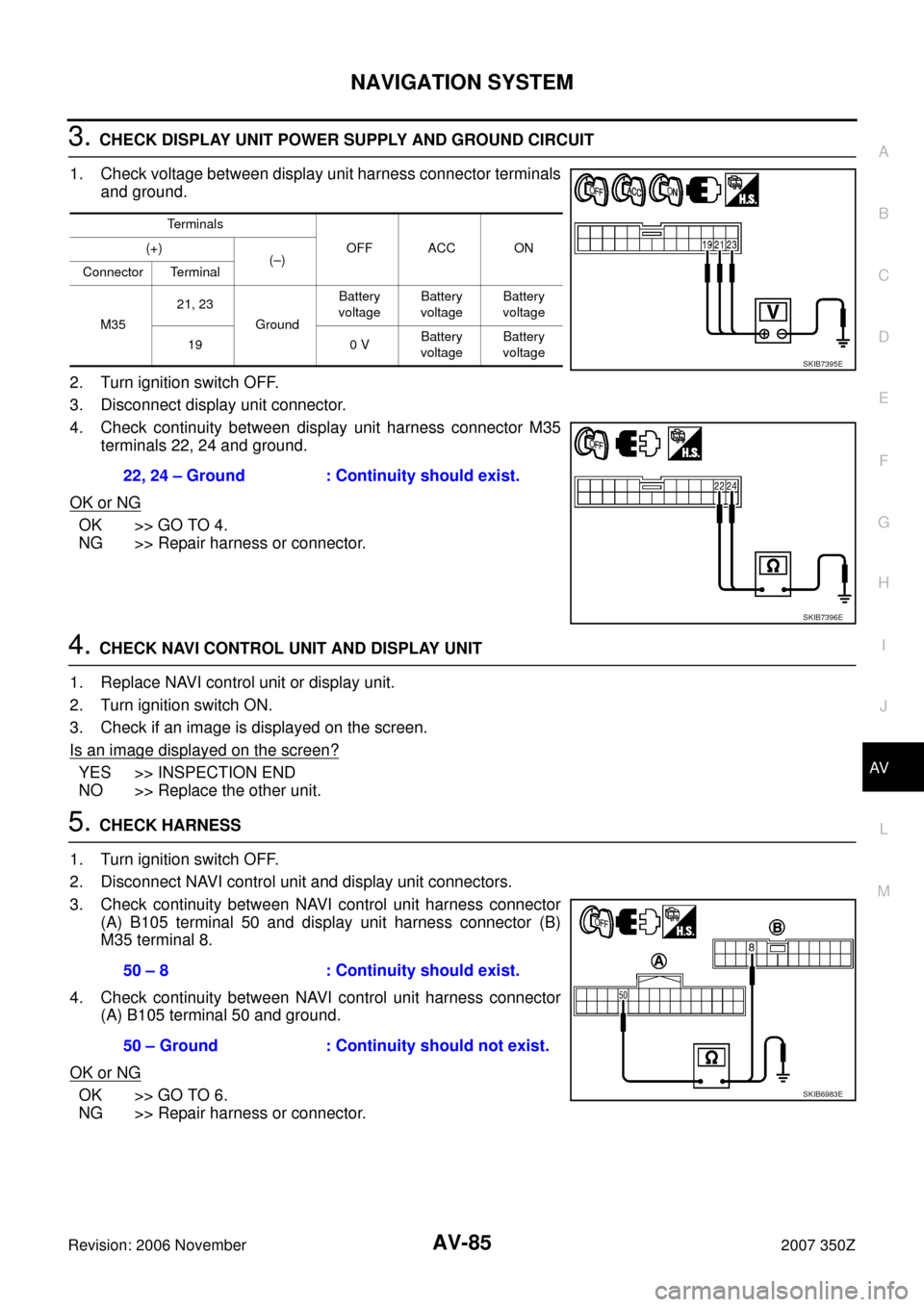
1. Check voltage between display unit harness connector terminals
and ground.
2. Turn ignition switch OFF.
3. Disconnect display unit connector.
4. Check continuity between display unit harness connector M35
terminals 22, 24 and ground.
OK or NG
OK >> GO TO 4.
NG >> Repair harness or connector.
4. CHECK NAVI CONTROL UNIT AND DISPLAY UNIT
1. Replace NAVI control unit or display unit.
2. Turn ignition switch ON.
3. Check if an image is displayed on the screen.
Is an image displayed on the screen?
YES >> INSPECTION END
NO >> Replace the other unit.
5. CHECK HARNESS
1. Turn ignition switch OFF.
2. Disconnect NAVI control unit and display unit connectors.
3. Check continuity between NAVI control unit harness connector
(A) B105 terminal 50 and display unit harness connector (B)
M35 terminal 8.
4. Check continuity between NAVI control unit harness connector
(A) B105 terminal 50 and ground.
OK or NG
OK >> GO TO 6.
NG >> Repair harness or connector.
Terminals
OFF ACC ON (+)
(–)
Connector Terminal
M3521, 23
GroundBattery
voltageBattery
voltageBattery
voltage
19 0 VBattery
voltageBattery
voltage
22, 24 – Ground : Continuity should exist.
SKIB7395E
SKIB7396E
50 – 8 : Continuity should exist.
50 – Ground : Continuity should not exist.
SKIB6983E
Page 87 of 116

NAVIGATION SYSTEM
AV-87
C
D
E
F
G
H
I
J
L
MA
B
AV
Revision: 2006 November2007 350Z
Navigation System Is Not Operated by NAVI SwitchNKS000DJ
Symptom: Initial screen (NISSAN screen) or warning screen is displayed after ignition switch turns ON. But
NAVI switch does not work.
1. CHECK NAVI SWITCH POWER SUPPLY AND GROUND CIRCUIT
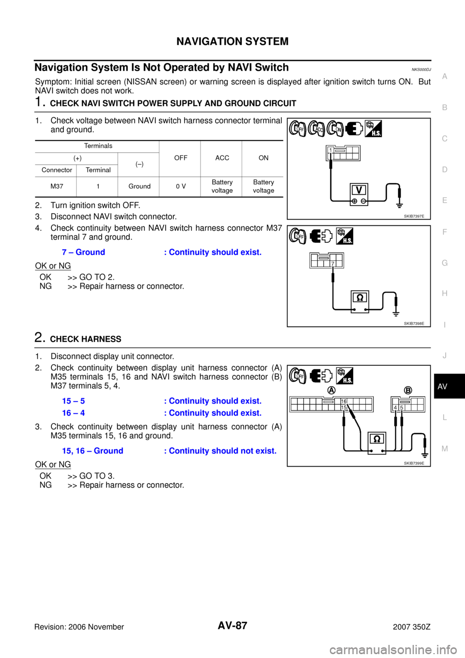
1. Check voltage between NAVI switch harness connector terminal
and ground.
2. Turn ignition switch OFF.
3. Disconnect NAVI switch connector.
4. Check continuity between NAVI switch harness connector M37
terminal 7 and ground.
OK or NG
OK >> GO TO 2.
NG >> Repair harness or connector.
2. CHECK HARNESS
1. Disconnect display unit connector.
2. Check continuity between display unit harness connector (A)
M35 terminals 15, 16 and NAVI switch harness connector (B)
M37 terminals 5, 4.
3. Check continuity between display unit harness connector (A)
M35 terminals 15, 16 and ground.
OK or NG
OK >> GO TO 3.
NG >> Repair harness or connector.
Terminals
OFF ACC ON (+)
(–)
Connector Terminal
M37 1 Ground 0 VBattery
voltageBattery
voltage
7 – Ground : Continuity should exist.
SKIB7397E
SKIB7398E
15 – 5 : Continuity should exist.
16 – 4 : Continuity should exist.
15, 16 – Ground : Continuity should not exist.
SKIB7399E