2007 MITSUBISHI LANCER EVOLUTION charging
[x] Cancel search: chargingPage 747 of 1449

ENGINE ELECTRICAL -Charging System16-15
"BAROTOR INSTALLATION
After installing the rotor, remove the wire used to fix the brush.
INSPECTION
ROTOR CHECK
1. Check the continuity between the rotor coil slip rings,
and replace the rotor if the resistance value is not at
the standard value.
Standard value: 3 - 5Ω
2. Check the continuity between the slip ring and core, and
if there is continuity, replace the rotor.
STATOR CHECK
1. Check the continuity between the coil leads, and if there
is continuity, replace the stator.
2. Check the continuity between the coil and core, and if
there is continuity, replace the stator.
Wire
Page 748 of 1449

ENGINE ELECTRICAL -Charging System16-16
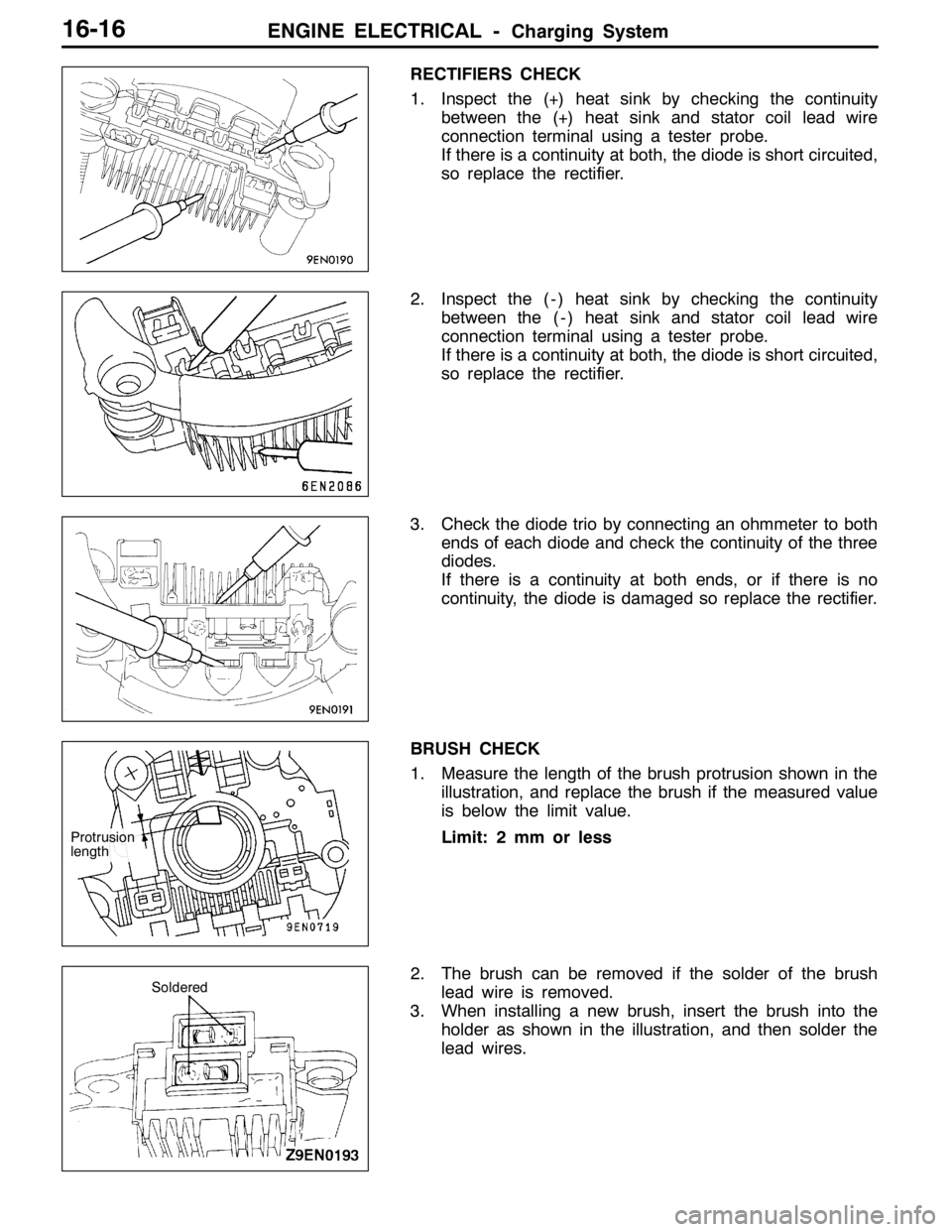
RECTIFIERS CHECK
1. Inspect the (+) heat sink by checking the continuity
between the (+) heat sink and stator coil lead wire
connection terminal using a tester probe.
If there is a continuity at both, the diode is short circuited,
so replace the rectifier.
2. Inspect the ( - ) heat sink by checking the continuity
between the ( - ) heat sink and stator coil lead wire
connection terminal using a tester probe.
If there is a continuity at both, the diode is short circuited,
so replace the rectifier.
3. Check the diode trio by connecting an ohmmeter to both
ends of each diode and check the continuity of the three
diodes.
If there is a continuity at both ends, or if there is no
continuity, the diode is damaged so replace the rectifier.
BRUSH CHECK
1. Measure the length of the brush protrusion shown in the
illustration, and replace the brush if the measured value
is below the limit value.
Limit: 2 mm or less
2. The brush can be removed if the solder of the brush
lead wire is removed.
3. When installing a new brush, insert the brush into the
holder as shown in the illustration, and then solder the
lead wires.
Protrusion
length
Soldered
Page 1322 of 1449

54A-2
CHASSIS
ELECTRICAL
CONTENTS
BATTERY 4..............................
SERVICE SPECIFICATION 4....................
ON-VEHICLE SERVICE 4......................
Fluid Level and Specific Gravity Check 4........
Charging 4.................................
Battery Testing Procedure 5...................
IGNITION SWITCH AND IMMOBILIZER
SYSTEM 6...............................
SPECIAL TOOLS 6............................
TROUBLESHOOTING 6........................
IMMOBILIZER-ECU CHECK 10.................
IGNITION SWITCH 11..........................
COMBINATION METER 14................
SERVICE SPECIFICATIONS 14.................
SEALANT 14..................................
SPECIAL TOOLS 15...........................
TROUBLESHOOTING 15.......................
ON-VEHICLE SERVICE 19.....................Speedometer Check 19......................
Tachometer Check 20........................
Fuel Gauge Unit Check 20....................
Engine Coolant Temperature Gauge
Unit Check 21...............................
COMBINATION METER 22.....................
HEADLAMP ASSEMBLY 24...............
SERVICE SPECIFICATIONS 24.................
TROUBLESHOOTING 24.......................
ON-VEHICLE SERVICE 24.....................
Headlamp Aiming 24.........................
Headlamp Intensity Measurement 28...........
Headlamp Bulb(low beam)Replacement28 ....
Headlamp Bulb(high beam)Replacement29 ...
Position Lamp Bulb Replacement29 ...........
Front Turn Signal Lamp Bulb Replacement29 ...
Headlamp Auto Cut Adjustment Procedure29 ...
HeadlampAuto Cut Function Check 29.........
HEADLAMP ASSEMBLY 30....................
CONTINUED ON NEXT PAGE
Page 1324 of 1449
![MITSUBISHI LANCER EVOLUTION 2007 Service Repair Manual CHASSIS ELECTRICAL -BatteryCHASSIS ELECTRICAL -Battery54A-4
BATTERY
SERVICE SPECIFICATION
ItemSpecification
Specific gravity of the battery fluid1.220 - 1.290 [20_C]
ON-VEHICLE SERVICE
FLUID LEVEL AND MITSUBISHI LANCER EVOLUTION 2007 Service Repair Manual CHASSIS ELECTRICAL -BatteryCHASSIS ELECTRICAL -Battery54A-4
BATTERY
SERVICE SPECIFICATION
ItemSpecification
Specific gravity of the battery fluid1.220 - 1.290 [20_C]
ON-VEHICLE SERVICE
FLUID LEVEL AND](/manual-img/19/57084/w960_57084-1323.png)
CHASSIS ELECTRICAL -BatteryCHASSIS ELECTRICAL -Battery54A-4
BATTERY
SERVICE SPECIFICATION
ItemSpecification
Specific gravity of the battery fluid1.220 - 1.290 [20_C]
ON-VEHICLE SERVICE
FLUID LEVEL AND SPECIFIC GRAVITY CHECK
1. Inspect whether or not the battery fluid is between the
UPPER LEVEL and LOWER LEVEL marks.
Caution
(1) If the battery fluid is below the LOWER LEVEL,
the battery could explode in using.
(2) If the battery fluid is over the UPPER LEVEL,
leakage could result.
2. Use a hydrometer and thermometer to check the specific
gravity of the battery fluid.
Standard value: 1.220 - 1.290 [20_C]
The specific gravity of the battery fluid varies with the
temperature, so use the following formula to calculate
the specific gravity for 20_C. Use the calculated value
to determine whether or not the specific gravity is
satisfactory.
D20 = (t - 20)×0.0007 + Dt
D20: Specific gravity of the battery fluid calculated
for 20_C.
Dt: Actually measured specific gravity
t: Actually measured temperature
CHARGING
1. Remove the battery from the vehicle.
2. The normal charging current is a value in amperes which is 1/10th of the battery capacity. If the
battery needs to be charged rapidly because of reasons such as time limitations, the maximum charging
current for rapid charging is the battery capacity expressed as an ampere value.
Battery typeCapacity (5-hour rate)Normal charging currentRapid charging current
44B2034 A3.4 A34 A
3. Determine when charging is finished.
DWhen the specific gravity of the battery electrolyte is constantly within 1.250 - 1.290 for a
continuous period of one hour or more
DWhen the voltage per cell during charging is 2.5 - 2.8 V constantly for a continuous period
of one hour or more
Thermometer
HydrometerGood
Page 1325 of 1449

CHASSIS ELECTRICAL -Battery54A-5
Caution
1. The battery plugs should be removed during charging.
2. The battery electrolyte level may rise and overflow from the battery during charging.
3. Explosions may occur if the battery is brought close to naked flames during charging.
4. Be careful to avoid tasks that might produce sparks or other danger while the battery is
charging.
5. After charging is complete, replace the battery plugs, pour water over the battery to rinse
away any sulphuric acid, and let the battery stand to dry.
6. Charge the battery in a well-ventilated location.
7. Do not let the battery electrolyte temperature rise above approximately 45_C
(approximately 55_Cduring rapid charging).
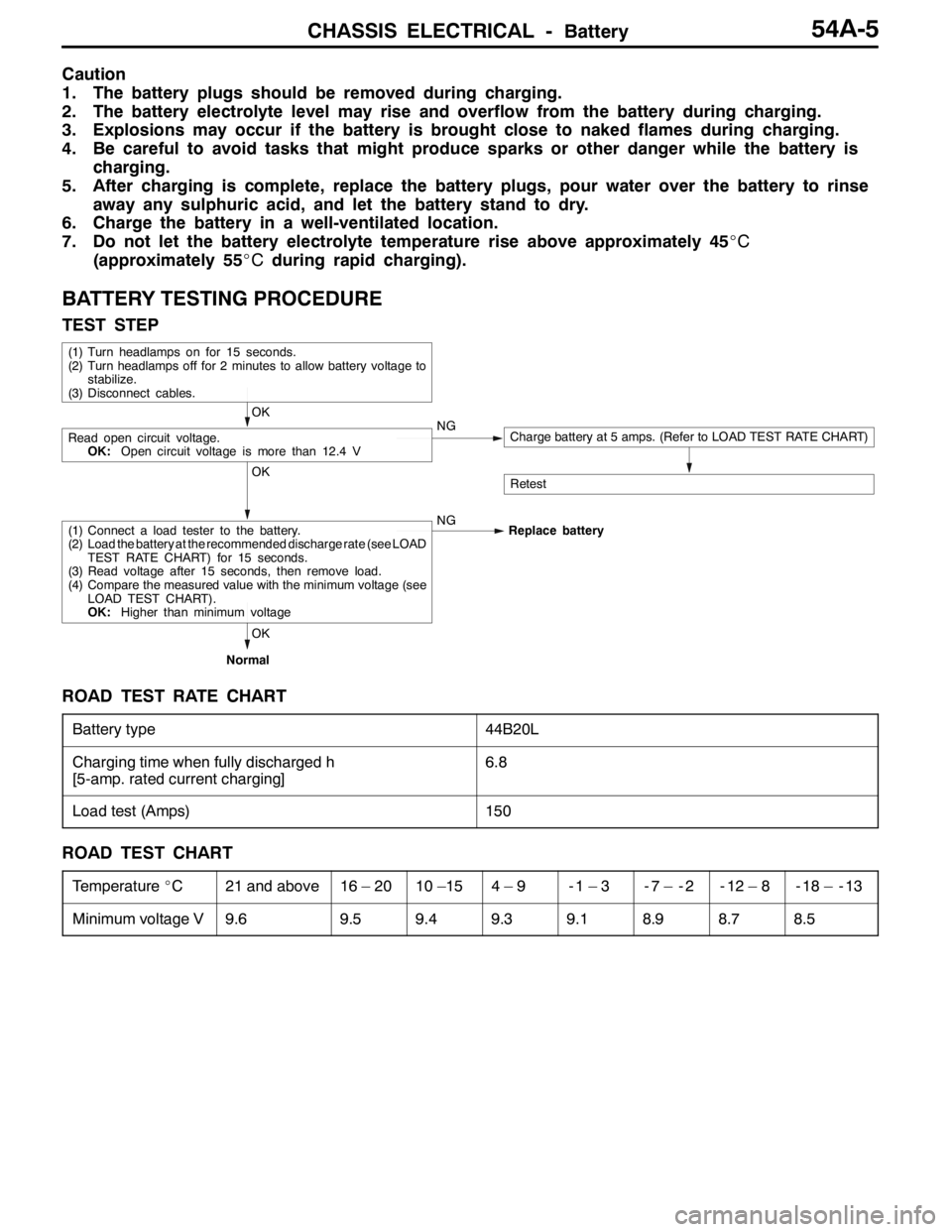
BATTERY TESTING PROCEDURE
TEST STEP
(1) Turn headlamps on for 15 seconds.
(2) Turn headlamps off for 2 minutes to allow battery voltage to
stabilize.
(3) Disconnect cables.
OK
Read open circuit voltage.
OK:Open circuit voltage is more than 12.4 VNGCharge battery at 5 amps. (Refer to LOAD TEST RATE CHART)
RetestOK
(1) Connect a load tester to the battery.
(2) Load the battery at the recommended discharge rate (see LOAD
TEST RATE CHART) for 15 seconds.
(3) Read voltage after 15 seconds, then remove load.
(4) Compare the measured value with the minimum voltage (see
LOAD TEST CHART).
OK:Higher than minimum voltageNG
Replace battery
OK
Normal
ROAD TEST RATE CHART
Battery type44B20L
Charging time when fully discharged h
[5-amp. rated current charging]6.8
Load test (Amps)150
ROAD TEST CHART
Temperature_C21 and above16 – 2010 –154–9-1–3-7 – -2-12 – 8-18 – -13
Minimum voltage V9.69.59.49.39.18.98.78.5
Page 1348 of 1449

CHASSIS ELECTRICAL -Headlamp Assembly54A-28
HEADLAMP INTENSITY MEASUREMENT
1. Using a photometer, and following its manufacture’s
instruction manual.
2. Maintain an engine speed of 2,000 r/min., with the battery
in the charging condition
3. Set the headlamps to high beam
4. Measure the headlamp centre intensity (a point of H line
and V line) and check to be sure that the limit value
is satisfied.
Limit:
High beam 30,000 cd or more per one headlamp
NOTE
1. There may be special local regulations pertaining to
headlamp intensity, be sure to make any adjustments
necessary to satisfy such regulations.
2. If an illuminometer is used to make the measurements,
convert its values to photometer values by using the
following formula.
I=Er
2Where:
I=intensity (cd)
E=illumination (lux)
r=distance (m) from headlamps to illuminometer
Caution
1. On the headlamp not yet adjusted, perform aiming
with connector removed and the lamps switched off,
if applicable. In addition, care should be taken to
prevent a change of optical axis when connector is
reconnected.
2. Plastic outer lens are equipped with headlamps. When
lens surface is covered with materials for not
penetrating light, headlamp operation time should be
within 3 minutes. In addition, masking such as taping
should not be performed.
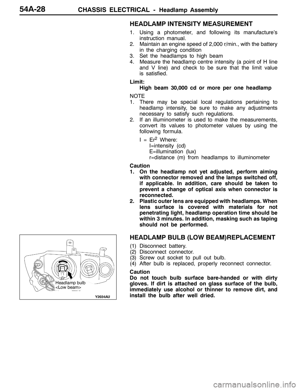
HEADLAMP BULB (LOW BEAM)REPLACEMENT
(1) Disconnect battery.
(2) Disconnect connector.
(3) Screw out socket to pull out bulb.
(4) After bulb is replaced, properly reconnect connector.
Caution
Do not touch bulb surface bare-handed or with dirty
gloves. If dirt is attached on glass surface of the bulb,
immediately use alcohol or thinner to remove dirt, and
install the bulb after well dried.
Headlamp bulb
Page 1363 of 1449

CHASSIS ELECTRICAL -Defogger54A-43
ON-VEHICLE SERVICE
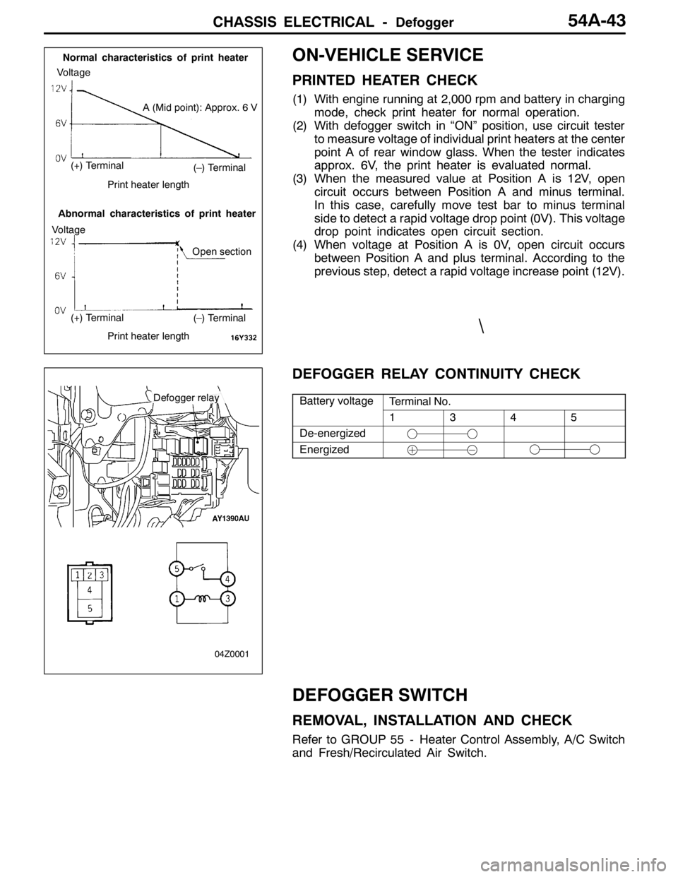
PRINTED HEATER CHECK
(1) With engine running at 2,000 rpm and battery in charging
mode, check print heater for normal operation.
(2) With defogger switch in “ON” position, use circuit tester
to measure voltage of individual print heaters at the center
point A of rear window glass. When the tester indicates
approx. 6V, the print heater is evaluated normal.
(3) When the measured value at Position A is 12V, open
circuit occurs between Position A and minus terminal.
In this case, carefully move test bar to minus terminal
side to detect a rapid voltage drop point (0V). This voltage
drop point indicates open circuit section.
(4) When voltage at Position A is 0V, open circuit occurs
between Position A and plus terminal. According to the
previous step, detect a rapid voltage increase point (12V).
DEFOGGER RELAY CONTINUITY CHECK
Battery voltageTerminal No.yg
1345
De-energized
Energized
DEFOGGER SWITCH
REMOVAL, INSTALLATION AND CHECK
Refer to GROUP 55 - Heater Control Assembly, A/C Switch
and Fresh/Recirculated Air Switch.
(–) Terminal
(–) Terminal
A (Mid point): Approx. 6 V
Normal characteristics of print heater
Abnormal characteristics of print heater
Voltage
Voltage
(+) Terminal
(+) Terminal
Print heater length
Print heater length
Open section
Defogger relay
04Z0001
\
Page 1403 of 1449

55-1
HEATER, AIR
CONDITIONER AND
VENTILATION
CONTENTS
SERVICE SPECIFICATIONS 2.................
LUBRICANTS 2..............................
SPECIAL TOOLS 2...........................
TROUBLESHOOTING 3.......................
ON-VEHICLE SERVICE 14....................
Refrigerant Level Test through Performance Test 14.
Magnetic Clutch Test 14.........................
Receiver Drier Test 14..........................
Compressor Drive Belt Adjustment 15.............
Dual Pressure Switch Check 15..................
Charging 16...................................
Correcting Low Refrigerant Level in case the Service
can used 18...................................
Discharging System 19..........................
Refilling of Oil in the A/C System 19...............
Performance Test 20............................
Refrigerant Leak Repair 21......................
Blower Relay Continuity Check 22................
A/C Compressor Relay Continuity Check 22........Condenser Fan Relay (LO) Check 23.............
Condenser Fan Relay (HI) Check 23..............
Idle-up Operation Check 24.....................
HEATER CONTROL ASSEMBLY (A/C-ECU)
AND A/C SWITCH 25........................
HEATER UNIT AND BLOWER ASSEMBLY 28.
REGISTOR, BLOWER MOTOR AND
INSIDE/OUTSIDE AIR CHANGE OVER
DAMPER MOTOR 32.........................
EVAPORATOR AND AIR THERMO SENSOR
34 ...........................................
COMPRESSOR 36............................
CONDENSER ASSEMBLY AND CONDENSER
FAN ASSEMBLY 40...........................
REFRIGERANT LINES 42.....................
DUCTS 44...................................
VENTILATION 45.............................