Page 735 of 1449
ENGINE ELECTRICAL -Charging System16-3
ALTERNATOR SPECIFICATIONS
ItemsSpecifications
TypeBattery voltage sensing
Rated output V/A12/90
Voltage regulatorElectronic built-in type
SERVICE SPECIFICATIONS
ItemsStandard valueLimit
Alternator output line voltage drop (at 30 A) V-max. 0.3
Regulated voltage ambient
tempatvoltageregulatorV
-20_C14.2 - 15.4-
temp. atvoltage regulatorV
20_C13.9 - 14.9-
60_C13.4 - 14.6-
80_C13.1 - 14.5-
Output current-70 % of normal output current
Rotor coil resistanceΩApprox. 3 - 5-
Protrusion length of brush mm-2
SPECIAL TOOL
ToolNumberNameUse
MB991519Alternator test
harnessChecking the alternator (S terminal voltage)
Page 748 of 1449
ENGINE ELECTRICAL -Charging System16-16
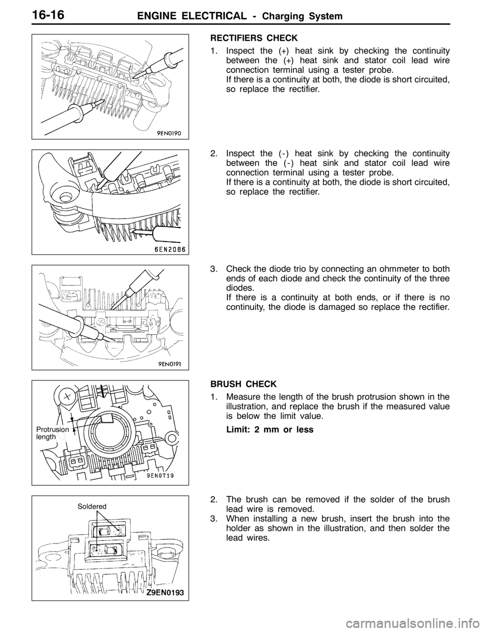
RECTIFIERS CHECK
1. Inspect the (+) heat sink by checking the continuity
between the (+) heat sink and stator coil lead wire
connection terminal using a tester probe.
If there is a continuity at both, the diode is short circuited,
so replace the rectifier.
2. Inspect the ( - ) heat sink by checking the continuity
between the ( - ) heat sink and stator coil lead wire
connection terminal using a tester probe.
If there is a continuity at both, the diode is short circuited,
so replace the rectifier.
3. Check the diode trio by connecting an ohmmeter to both
ends of each diode and check the continuity of the three
diodes.
If there is a continuity at both ends, or if there is no
continuity, the diode is damaged so replace the rectifier.
BRUSH CHECK
1. Measure the length of the brush protrusion shown in the
illustration, and replace the brush if the measured value
is below the limit value.
Limit: 2 mm or less
2. The brush can be removed if the solder of the brush
lead wire is removed.
3. When installing a new brush, insert the brush into the
holder as shown in the illustration, and then solder the
lead wires.
Protrusion
length
Soldered
Page 749 of 1449
ENGINE ELECTRICAL -Starting System16-17
STARTING SYSTEM
GENERAL INFORMATION
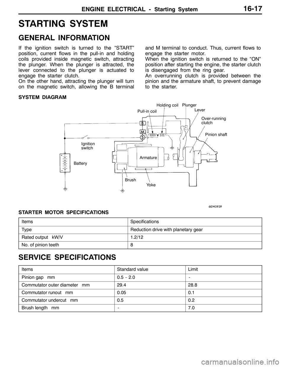
If the ignition switch is turned to the “START”
position, current flows in the pull-in and holding
coils provided inside magnetic switch, attracting
the plunger. When the plunger is attracted, the
lever connected to the plunger is actuated to
engage the starter clutch.
On the other hand, attracting the plunger will turn
on the magnetic switch, allowing the B terminaland M terminal to conduct. Thus, current flows to
engage the starter motor.
When the ignition switch is returned to the “ON”
position after starting the engine, the starter clutch
is disengaged from the ring gear.
An overrunning clutch is provided between the
pinion and the armature shaft, to prevent damage
to the starter.
SYSTEM DIAGRAM
Pull-in coilHolding coil
Ignition
switch
BatteryArmature
Brush
YokePlunger
Lever
Over-running
clutch
Pinion shaft
STARTER MOTOR SPECIFICATIONS
ItemsSpecifications
TypeReduction drive with planetary gear
Rated output kW/V1.2/12
No. of pinion teeth8
SERVICE SPECIFICATIONS
ItemsStandard valueLimit
Pinion gap mm0.5 - 2.0-
Commutator outer diameter mm29.428.8
Commutator runout mm0.050.1
Commutator undercut mm0.50.2
Brush length mm-7.0
Page 756 of 1449
ENGINE ELECTRICAL -Starting System16-24
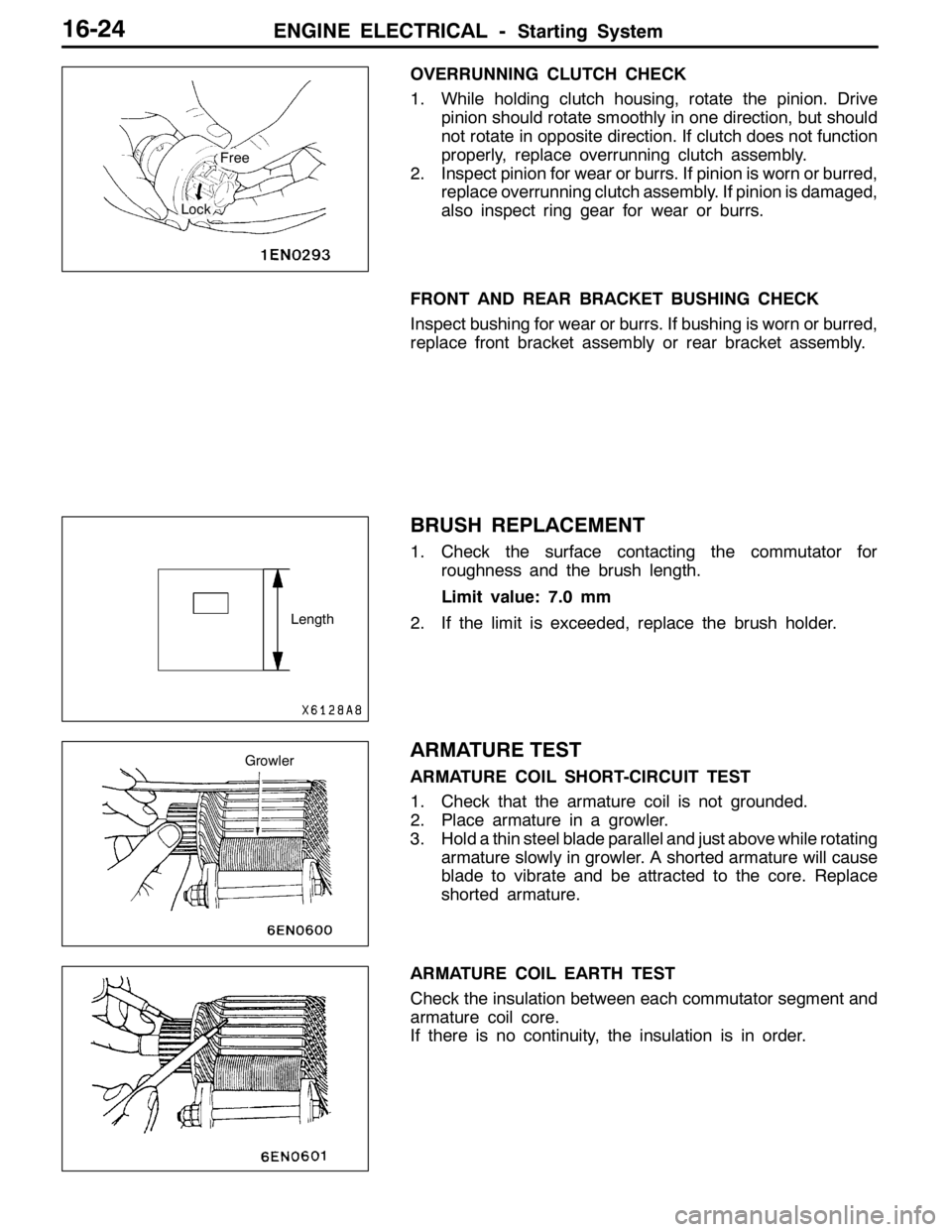
OVERRUNNING CLUTCH CHECK
1. While holding clutch housing, rotate the pinion. Drive
pinion should rotate smoothly in one direction, but should
not rotate in opposite direction. If clutch does not function
properly, replace overrunning clutch assembly.
2. Inspect pinion for wear or burrs. If pinion is worn or burred,
replace overrunning clutch assembly. If pinion is damaged,
also inspect ring gear for wear or burrs.
FRONT AND REAR BRACKET BUSHING CHECK
Inspect bushing for wear or burrs. If bushing is worn or burred,
replace front bracket assembly or rear bracket assembly.
BRUSH REPLACEMENT
1. Check the surface contacting the commutator for
roughness and the brush length.
Limit value: 7.0 mm
2. If the limit is exceeded, replace the brush holder.
ARMATURE TEST
ARMATURE COIL SHORT-CIRCUIT TEST
1. Check that the armature coil is not grounded.
2. Place armature in a growler.
3. Hold a thin steel blade parallel and just above while rotating
armature slowly in growler. A shorted armature will cause
blade to vibrate and be attracted to the core. Replace
shorted armature.
ARMATURE COIL EARTH TEST
Check the insulation between each commutator segment and
armature coil core.
If there is no continuity, the insulation is in order.
Free
Lock
Length
Growler
Page 764 of 1449

ENGINE ELECTRICAL -Ignition System16-32
WAVEFORM OBSERVATION POINTS
Point A: The height, length and slope of the spark line show the following trends (Refer to abnormal
waveform examples, 1, 2, 3 and 4).
Spark linePlug gapCondition of
electrodeCompression
forceConcentration of
air mixtureIgnition timingSpark plug
cable
LengthLongSmallNormalLowRichAdvancedLeak
ShortLargeLarge wearHighLeanRetardedHigh
resistance
HeightHighLargeLarge wearHighLeanRetardedHigh
resistance
LowSmallNormalLowRichAdvancedLeak
SlopeLargePlug is fouled----
Point B: Number of vibration in reduction vibration section (Refer to abnormal waveform example 5)
Number of vibrationsCoil and condenser
Three or moreNormal
Except aboveAbnormal
Point C: Number of vibrations at beginning of dwell section (Refer to abnormal waveform example 5)
Number of vibrationsCoil
5 - 6 or higherNormal
Except aboveAbnormal
Point D: Ignition voltage height (distribution per each cylinder) shows the following trends.
Ignition
voltagePlug gapCondition of
electrodeCompression
forceConcentration of
air mixtureIgnition timingSpark plug cable
HighLargeLarge wearHighLeanRetardedHigh resistance
LowSmallNormalLowRichAdvancedLeak
Page 799 of 1449
CLUTCH -Clutch Control21A-9
DISASSEMBLY AND REASSEMBLY
CLUTCH MASTER CYLINDER
Caution
Do not disassemble piston assembly.
1
4 5
27
223
4
Grease: Rubber grease
Clutch fluid:
Brake fluid DOT3 or DOT4
Piston repair kit
13±2 N·m
12
3
6
8
4 5
8
Disassembly steps
1. Piston stopper ring
2. Piston assembly
"AA3. Push rod assembly
4. Boot5. Spring pin
6. Reservoir tank
7. Seal
8. Master cylinder body
INSTALLATION SERVICE POINT
"AAPUSH ROD ASSEMBLY INSTALLATION
Set the length of the push rod assembly to the shown
dimension to make the adjustment of clutch pedal easier.
104.3±0.5 mm
Page 930 of 1449
FRONT AXLE -General Information26-2
GENERAL INFORMATION
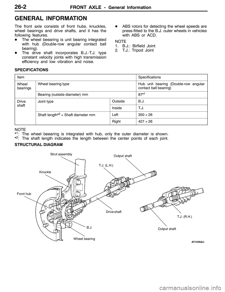
The front axle consists of front hubs, knuckles,
wheel bearings and drive shafts, and it has the
following features.
DThe wheel beearing is unit bearing integrated
with hub (Double-row angular contact ball
bearing).
DThe drive shaft incorporates B.J.-T.J. type
constant velocity joints with high transmission
efficiency and low vibration and noise.DABS rotors for detecting the wheel speeds are
press-fitted to the B.J. outer wheels in vehicles
with ABS or ACD.
NOTE
1. B.J.: Birfield Joint
2. T.J.: Tripod Joint
SPECIFICATIONS
ItemSpecifications
Wheel
bearingsWheel bearing typeHub unit bearing (Double-row angular
contact ball bearing)
g
Bearing (outside diameter) mm87*1
Drive
shaft
Joint typeOutsideB.J.
shaftInsideT.J.
Shaft length*2×Shaft diameter mmLeft350×26
Right427×26
NOTE
*1: The wheel beearing is integrated with hub, only the outer diameter is shown.
*2: The shaft length indicates the length between the center points of each joint.
STRUCTURAL DIAGRAM
B.J.T. J . KnuckleOutput shaft Strut assembly
Drive shaft
Wheel bearing Front hubT.J. (L.H.)
Output shaftT.J. (R.H.)
Page 931 of 1449
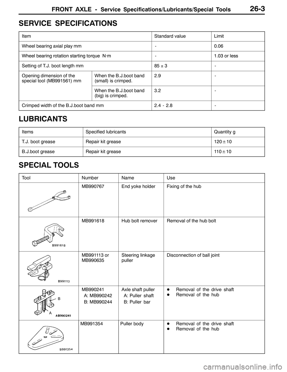
FRONT AXLE -Service Specifications/Lubricants/Special Tools26-3
SERVICE SPECIFICATIONS
ItemStandard valueLimit
Wheel bearing axial play mm-0.06
WheelbearingrotationstartingtorqueN·m-103orlessWheelbearing rotation startingtorqueN·m-1.03orless
Setting of T.J. boot length mm85±3-
Opening dimension of the
special tool (MB991561) mmWhen the B.J.boot band
(small) is crimped.2.9-
When the B.J.boot band
(big) is crimped.3.2-
Crimped width of the B.J.boot band mm2.4 - 2.8-
LUBRICANTS
ItemsSpecified lubricantsQuantity g
T.J. boot greaseRepair kit grease120±10
B.J.boot greaseRepair kit grease11 0±10
SPECIAL TOOLS
ToolNumberNameUse
MB990767End yoke holderFixing of the hub
MB991618Hub bolt removerRemoval of the hub bolt
MB991113 or
MB990635Steering linkage
pullerDisconnection of ball joint
A
B
MB990241
A: MB990242
B: MB990244Axle shaft puller
A: Puller shaft
B: Puller barDRemoval of the drive shaft
DRemoval of the hub
MB991354Puller bodyDRemoval of the drive shaft
DRemoval of the hub