2007 MITSUBISHI LANCER EVOLUTION coolant level
[x] Cancel search: coolant levelPage 435 of 1449
ENGINE -Cylinder Head Gasket11A-29
5.0±1.0 N·m
61
2
3 4
57
8
910
11 12
1314
13±1 N·m
15
16
17
5.0±1.0 N·m
1819
9.0±1.0 N·m
9.0±1.0 N·m
(Engine oil)
1
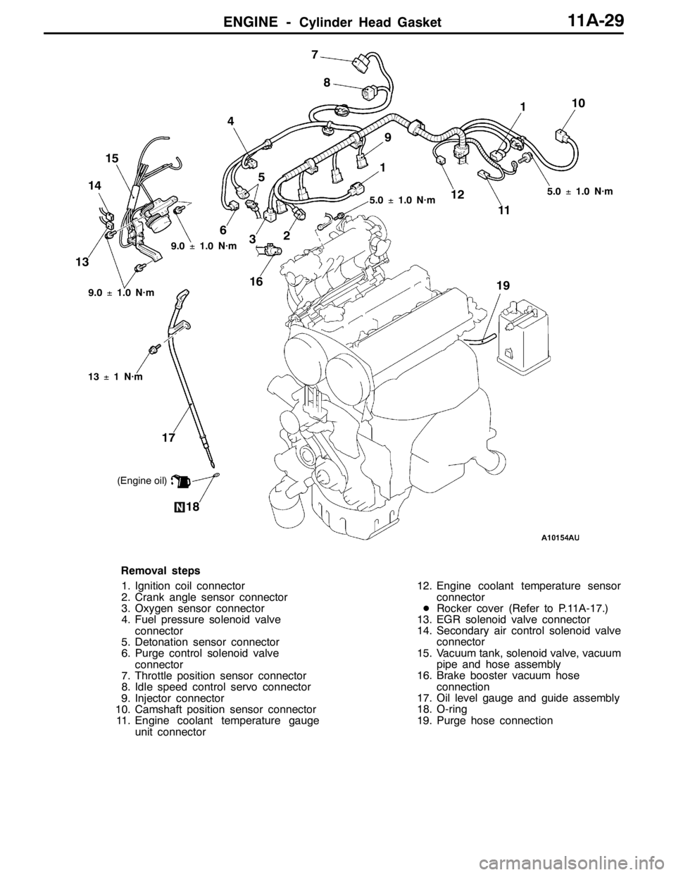
Removal steps
1. Ignition coil connector
2. Crank angle sensor connector
3. Oxygen sensor connector
4. Fuel pressure solenoid valve
connector
5. Detonation sensor connector
6. Purge control solenoid valve
connector
7. Throttle position sensor connector
8. Idle speed control servo connector
9. Injector connector
10. Camshaft position sensor connector
11. Engine coolant temperature gauge
unit connector12. Engine coolant temperature sensor
connector
DRocker cover (Refer to P.11A-17.)
13. EGR solenoid valve connector
14. Secondary air control solenoid valve
connector
15. Vacuum tank, solenoid valve, vacuum
pipe and hose assembly
16. Brake booster vacuum hose
connection
17. Oil level gauge and guide assembly
18. O-ring
19. Purge hose connection
Page 528 of 1449
ENGINE LUBRICATION -On-vehicle Service12-4
ON-VEHICLE SERVICE
ENGINE OIL CHECK
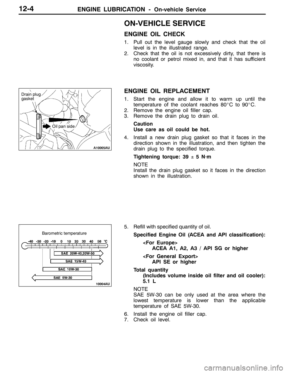
1. Pull out the level gauge slowly and check that the oil
level is in the illustrated range.
2. Check that the oil is not excessively dirty, that there is
no coolant or petrol mixed in, and that it has sufficient
viscosity.
ENGINE OIL REPLACEMENT
1. Start the engine and allow it to warm up until the
temperature of the coolant reaches 80_Cto90_C.
2. Remove the engine oil filler cap.
3. Remove the drain plug to drain oil.
Caution
Use care as oil could be hot.
4. Install a new drain plug gasket so that it faces in the
direction shown in the illustration, and then tighten the
drain plug to the specified torque.
Tightening torque: 39±5 N·m
NOTE
Install the drain plug gasket so it faces in the direction
shown in the illustration.
5. Refill with specified quantity of oil.
Specified Engine Oil (ACEA and API classification):
ACEA A1, A2, A3 / API SG or higher
API SE or higher
Total quantity
(Includes volume inside oil filter and oil cooler):
5.1 L
NOTE
SAE 5W-30 can be only used at the area where the
lowest temperature is lower than the applicable
temperature of SAE 5W-30.
6. Install the engine oil filler cap.
7. Check oil level.
Drain plug
gasket
Oil pan side
Barometric temperature
Page 611 of 1449
MPI -Troubleshooting13A-79
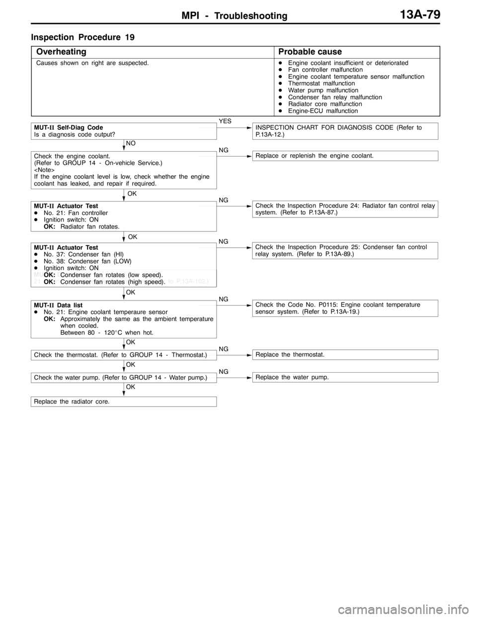
Inspection Procedure 19
Overheating
Probable cause
Causes shown on right are suspected.DEngine coolant insufficient or deteriorated
DFan controller malfunction
DEngine coolant temperature sensor malfunction
DThermostat malfunction
DWater pump malfunction
DCondenser fan relay malfunction
DRadiator core malfunction
DEngine-ECU malfunction
NO
NG
Replace or replenish the engine coolant.
OK
Replace the radiator core.
OK
Check the water pump. (Refer to GROUP 14 - Water pump.)NGReplace the water pump.
OK
Check the thermostat. (Refer to GROUP 14 - Thermostat.)NGReplace the thermostat.
OK
MUT-IIData list
DNo. 21: Engine coolant temperaure sensor
OK:Approximately the same as the ambient temperature
when cooled.
Between 80 - 120_C when hot.NGCheck the Code No. P0115: Engine coolant temperature
sensor system. (Refer to P.13A-19.)
MUT-IIData list
21 Engine coolant temperature sensor (Refer to P.13A-102.)
OK
MUT-IIActuator Test
DNo. 37: Condenser fan (HI)
DNo. 38: Condenser fan (LOW)
DIgnition switch: ON
OK:Condenser fan rotates (low speed).
OK:Condenser fan rotates (high speed).NGCheck the Inspection Procedure 25: Condenser fan control
relay system. (Refer to P.13A-89.)
MUT-IIActuator Test
DNo. 21: Fan controller
DIgnition switch: ON
OK:Radiator fan rotates.NGCheck the Inspection Procedure 24: Radiator fan control relay
system. (Refer to P.13A-87.)
OK
Check the engine coolant.
(Refer to GROUP 14 - On-vehicle Service.)
If the engine coolant level is low, check whether the engine
coolant has leaked, and repair if required.
MUT-IISelf-Diag Code
Is a diagnosis code output?YESINSPECTION CHART FOR DIAGNOSIS CODE (Refer to
P.13A-12.)
Page 694 of 1449

ENGINE COOLING -On-vehicle Service14-6
ON-VEHICLE SERVICE
ENGINE COOLANT LEAK CHECKING
1. Confirm that the coolant level is up to the filler neck.
Install a radiator cap tester and apply 160 kPa pressure,
and then check for leakage from the radiator hose or
connections.
Caution
(1) Be sure to completely clean away any moisture
from the places checked.
(2) When the tester is taken out, be careful not to
spill any coolant from it.
(3) Be careful, when installing and removing the tester
and when testing, not to deform the filler neck
of the radiator.
2. If there is leakage, repair or replace the appropriate part.
RADIATOR CAP OPENING PRESSURE CHECK
1. Use a cap adapter to attach the cap to the tester.
2. Increase the pressure until the indicator of the gauge
stops moving.
Limit: 83 kPa
Standard value: 93 - 123 kPa
3. Replace the radiator cap if the reading does not remain
at or above the limit.
NOTE
Be sure that the cap is clean before testing, since rust
or other foreign material on the cap seal will cause an
improper indication.
ENGINE COOLANT REPLACEMENT
1. Remove the under cover.
(Refer to GROUP 51 - Front Bumper.)
2. Drain the engine coolant by removing the drain plug and
then the radiator cap.
Cap adapter
Adapter
Cap adapter
Page 695 of 1449

ENGINE COOLING -On-vehicle ServiceENGINE COOLING -On-vehicle Service14-7
3. Remove the cylinder block drain plug from the cylinder
block to drain the engine coolant.
4. Remove the reserve tank to drain the engine coolant.
5. When the engine coolant has drained, pour in water from
the radiator cap to clean the engine coolant line.
6. Coat the thread of the cylinder block drain plug with the
specified sealant and tighten to the specified torque.
Specified sealant:
3M Nut Locking Part No. 4171 or equivalent
7. Securely tighten the radiator drain plug.
8. Install the under cover.
(Refer to GROUP 51 - Front Bumper.)
9. Install the reserve tank.
10. Slowly pour the engine coolant into the mouth of the
radiator until the radiator is full, and pour also into the
reserve tank up to the FULL line.
Recommended anti-freeze:
MITUBISHI GENUINE COOLANT or equivalent
Quantity: 6.0 L
Caution
Do not use alcohol or methanol anti-freeze or any
engine coolants mixed with alcohol or methanol
anti-freeze. The use of an improper anti-freeze can
cause the corrosion of the aluminium components.
11. Install the radiator cap securely.
12. Start the engine and warm the engine until the thermostat
opens. (Touch the radiator hose with your hand to check
that warm water is flowing.)
13. After the thermostat opens, race the engine several times,
and then stop the engine.
14. Cool down the engine, and then pour engine coolant into
the reserve tank until the level reaches the FULL line. If
the level is low, repeat the operation from step 11.
CONCENTRATION MEASUREMENT
Measure the temperature and specific gravity of the engine
coolant to check the antifreeze concentration.
Standard value: 30 - 60 % (allowable concentration range)
RECOMMENDED ANTI-FREEZE
AntifreezeAllowable concentration
MITSUBISHI GENUINE COOLANT
or equivalent30 - 60 %
Caution
If the concentration of the anti-freeze is below 30 %, the
anti-corrosion property will be adversely affected. In
addition, if the concentration is above 60 %, both the
anti-freezing and engine cooling properties will decrease,
affecting the engine adversely. For these reasons, be
sure to maintain the concentration level within the
specified range.
44±5N·m
Water inlet
pipe
Page 722 of 1449
INTAKE AND EXHAUST -Intake Manifold15-16
INTAKE MANIFOLD
REMOVAL AND INSTALLATION
Pre-removal and Post-installation Operation
DAir Duct Removal and Installation (Refer to P.15-8.)
DStrut Tower Bar Removal and Installation
(Refer to GROUP 42.)
DUnder Cover Removal and Installation
(Refer to GROUP 51 - Front Bumper.)
DEngine Coolant Draining and Supplying
(Refer to GROUP 14 - On-vehicle Service.)
DThrottle Body Removal and Installation (Refer to
GROUP 13A - Throttle Body.)DCrossmember Bar Removal and Installation (Refer
to GROUP 32 - Engine Roll Stopper, Centermember.)
DFront Exhaust Pipe Removal and Installation (Refer
to GROUP 15 - Exhaust Pipe and Main Muffler.)
DSecondary Air Control Valve Bracket Removal and
Installation (Refer to P.15-14.)
DEngine Oil Draining and Supplying
1
2
3 4
5 6 7
8 10
11
1214
13
15
16 17
18
9
11±1 N·m3.0±0.5 N·m
13±1 N·m
(Engine oil)
(Engine oil) 5.0±1.0 N·m
14 8
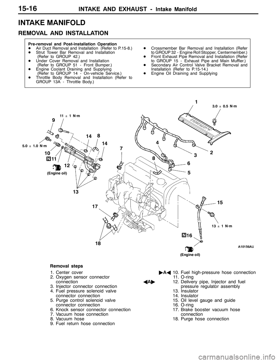
Removal steps
1. Center cover
2. Oxygen sensor connector
connection
3. Injector connector connection
4. Fuel pressure solenoid valve
connector connection
5. Purge control solenoid valve
connector connection
6. Knock sensor connector connection
7. Vacuum hose connection
8. Vacuum hose
9. Fuel return hose connection"AA10. Fuel high-pressure hose connection
11. O-ring
AA"12. Delivery pipe, Injector and fuel
pressure regulator assembly
13. Insulator
14. Insulator
15. Oil level gauge and guide
16. O-ring
17. Brake booster vacuum hose
connection
18. Purge hose connection
Page 780 of 1449
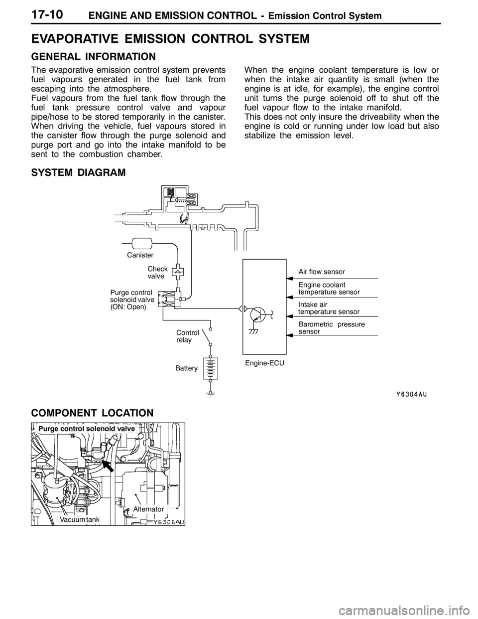
ENGINE AND EMISSION CONTROL -Emission Control System
Vacuum tank
Alternator
Purge control solenoid valve
17-10
EVAPORATIVE EMISSION CONTROL SYSTEM
GENERAL INFORMATION
The evaporative emission control system prevents
fuel vapours generated in the fuel tank from
escaping into the atmosphere.
Fuel vapours from the fuel tank flow through the
fuel tank pressure control valve and vapour
pipe/hose to be stored temporarily in the canister.
When driving the vehicle, fuel vapours stored in
the canister flow through the purge solenoid and
purge port and go into the intake manifold to be
sent to the combustion chamber.When the engine coolant temperature is low or
when the intake air quantity is small (when the
engine is at idle, for example), the engine control
unit turns the purge solenoid off to shut off the
fuel vapour flow to the intake manifold.
This does not only insure the driveability when the
engine is cold or running under low load but also
stabilize the emission level.
SYSTEM DIAGRAM
BatteryIntake air
temperature sensor
Barometric pressure
sensor
Check
valve
Canister
Control
relay
Purge control
solenoid valve
(ON: Open)
Engine-ECUEngine coolant
temperature sensor Air flow sensor
COMPONENT LOCATION
Page 783 of 1449

ENGINE AND EMISSION CONTROL -Emission Control System17-13
EXHAUST GAS RECIRCULATION (EGR) SYSTEM
GENERAL INFORMATION
The exhaust gas recirculation (EGR) system lowers
the nitrogen oxide (NOx) emission level. When the
air/fuel mixture combustion temperature is high,
a large quantity of nitrogen oxides (NOx) is
generated in the combustion chamber. Therefore,
this system recirculates part of emission gas fromthe exhaust port of the cylinder head to the
combustion chamber through the intake manifold
to decrease the air/fuel mixture combustion
temperature, resulting in reduction of NOx.
The EGR flow rate is controlled by the EGR valve
so as not to decrease the driveability.
OPERATION
The EGR valve is being closed and does not
recirculate exhaust gases under one of the following
conditions. Otherwise, the EGR valve is opened
and recirculates exhaust gases.DThe engine coolant temperature is low.
DThe engine is at idle.
DThe throttle valve is widely opened.
SYSTEM DIAGRAM
ON Throttle body
EGR control
solenoid valve
Engine
control
relay
Battery EGR valve
Crank angle sensor
Throttle position sensor Engine-ECU
Engine coolant
temperature sensor Air flow sensor