Page 520 of 705

519 Operation
Tires and wheels
General:
Depending on the design standards used,
the tire size molded into the sidewall may
have no letter or a letter preceding the tire
size designation.
No letter preceding the size designation
(as illustrated above): Passenger car tire
based on European design standards.
Letter “P” preceding the size designation:
Passenger car tire based on U.S. design
standards.
Letter “LT” preceding the size designation:
Light Truck tire based on U.S. design
standards.
Letter “T” preceding the size designation:
Temporary spare tires which are high
pressure compact spares designed for
temporary emergency use only. Tire width
The tire width1 (
�page 518) indicates
the nominal tire width in mm.
Aspect ratio
The aspect ratio2 (�page 518) is the
dimensional relationship between tire
section height and section width and is
expressed in percentage. The aspect ratio
is arrived at by dividing section height by
section width.
Tire code
The tire code3 (
�page 518) indicates
the tire construction type. The “R” stands
for radial tire type. Letter “D” means diag-
onal or bias ply construction; letter “B”
means belted-bias ply construction.
At the tire manufacturer’s option, any tire
with a speed capability above 149 mph
(240 km/h) can include a “ZR” in the size
designation (for example: 245/40 ZR 18).
For additional information, see “Tire speed
rating” (
�page 520).Rim diameter
The rim diameter4 (
�page 518) is the
diameter of the bead seat, not the
diameter of the rim edge. Rim diameter is
indicated in inches (in).
Tire load rating
The tire load rating5 (�page 518) is a
numerical code associated with the
maximum load a tire can support.
For example, a load rating of 91 corre-
sponds to a maximum load of 1 356 lbs
(615 kg) the tire is designed to support.
See also “Maximum tire load”
(
�page 523) where the maximum load as-
sociated with the load index is indicated in
kilograms and lbs.
Page 544 of 705
543 Practical hints
What to do if …?
Where will I find ...?
Unlocking/locking in an emergency
Opening/closing in an emergency
Resetting activated head restraints
(S 600 only)
Replacing SmartKey batteries
Replacing bulbs
Replacing wiper blades
Flat tire
Batteries
Jump starting
Towing the vehicle
Fuses
Page 548 of 705
547 Practical hints
What to do if …?
Problem
Possible cause/consequence
Suggested solution
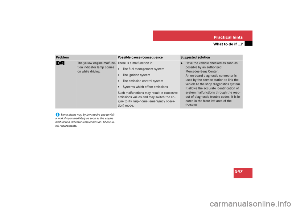
±
The yellow engine malfunc-
tion indicator lamp comes
on while driving.
There is a malfunction in:�
The fuel management system
�
The ignition system
�
The emission control system
�
Systems which affect emissions
Such malfunctions may result in excessive
emissions values and may switch the en-
gine to its limp-home (emergency opera-
tion) mode.
�
Have the vehicle checked as soon as
possible by an authorized
Mercedes-Benz Center.
An on-board diagnostic connector is
used by the service station to link the
vehicle to the shop diagnostics system.
It allows the accurate identification of
system malfunctions through the read-
out of diagnostic trouble codes. It is lo-
cated in the front left area of the
footwell.
i
Some states may by law require you to visit
a workshop immediately as soon as the engine
malfunction indicator lamp comes on. Check lo-
cal requirements.
Page 582 of 705

581 Practical hints
What to do if …?
Display
Possible cause/consequence
Possible solution
Please release
parking brake
The red indicator lamp for the electric park-
ing brake flashes and you also hear a warn-
ing tone.
You are driving with the electric parking
brake activated, or you are carrying out an
emergency brake application with the elec-
tric parking brake (
�page 364).
�
Release electric parking brake.
or
�
Carefully drive off (
�page 364).
or
�
Release the handle for electric parking brake.
(USA only)(Canada only)
Please release
parking brake
The red indicator lamp for the electric park-
ing brake flashes and the yellow warning
lamp for the electric parking brake comes
on. You also hear a warning tone.
The electric parking brake is malfunction-
ing; braking action is restricted.
While driving:�
Release the handle for electric parking brake.
While at a standstill:
�
Switch off ignition and press handle for elec-
tric parking brake until the warning message
disappears from the multifunction display.
Page 615 of 705
614 Practical hintsUnlocking/locking in an emergencyUnlocking the vehicle
If you are unable to unlock the vehicle with
the SmartKey or KEYLESS-GO*, open the
driver’s door and the trunk using the me-
chanical key. Removing the mechanical key
1Mechanical key locking tab
2Mechanical key
�
Move locking tab1 in the direction of
arrow.
�
Slide mechanical key2 out of the
housing.Unlocking the driver’s door
1Unlocking
2Mechanical key
�
Insert mechanical key2 into the driv-
er’s door lock until it stops.
�
Turn mechanical key2 counterclock-
wise to position1.
The driver’s door is unlocked.
�
Pull door handle quickly.
The locking knob moves up.
�
Turn back mechanical key2 and re-
move.
�
Pull door handle again.
i
Unlocking the driver’s door and/or the trunk
with the mechanical key will trigger the anti-theft
alarm system (
�page 75).
To cancel the alarm, insert the SmartKey or
SmartKey with KEYLESS-GO* in the starter
switch.
Page 616 of 705
 is required to open the trunk lid.
1Trunk lid lock�
Insert the mechanical key")
615 Practical hints
Unlocking/locking in an emergency
Unlocking the trunk
A minimum height clearance of 5.9 ft.
(1.80 m) is required to open the trunk lid.
1Trunk lid lock�
Insert the mechanical key into the
trunk lid lock1 until it stops.
�
Turn mechanical key all the way to the
left.
The trunk opens.
�
Turn the mechanical key back and re-
move it from the trunk lid lock.
Locking the vehicle
If you cannot lock the vehicle with the
SmartKey or KEYLESS-GO*, do the follow-
ing:�
Close the front passenger door, the
rear right door and the trunk.
�
Open the driver’s door and the rear left
door.
�
Press the central locking switch on the
driver’s door (
�page 314).
The locking knobs of the front passen-
ger door and the rear doors move
down.
If the vehicle battery is disconnected or
drained:
�
Press down the locking knobs of
the front passenger door and the
rear doors manually.
�
Exit the vehicle.
�
Close the driver’s door.
�
Enter the vehicle through the rear left
door.
�
Press down the locking knob of the
driver’s door.
�
Exit the vehicle.
�
Close the rear left door.
The vehicle is locked.
!
The trunk lid swings open upwards automat-
ically. Always make sure that there is sufficient
overhead clearance.
!
To prevent inadvertent lockout, make sure
to have the SmartKey or SmartKey with KEY-
LESS-GO* with you before proceeding with the
next step. The next step will lock the vehicle.
Page 617 of 705

616 Practical hintsUnlocking/locking in an emergencyMechanically releasing the electric parking brake
The mechanical release device for the
electric parking brake is underneath the
fuel filler flap next to the fuel cap.
1Fuel filler flap
2Release tool
3Protective cap
�
Shift the automatic transmission to P
(�page 367).
�
Place chock from vehicle tool kit
(�page 611) under a rear wheel.
�
Open fuel filler flap1.
�
Remove protective cap3.
�
Screw release tool2 from vehicle tool
kit clockwise 2 to 3 rotations onto re-
lease lever.
�
Pull release tool2 in direction of ar-
row.
The electric parking brake is released.
The red indicator lamp 0 (USA only)
or ! (Canada only) in the instru-
ment cluster for the electric parking
brake flashes. The message “Parking
brake See Oper. Manual” appears on
the driver’s display.
After it has been unlocked, you can engage
the electric parking brake again from the
driver’s seat.
�
Press the electric parking brake handle
(�page 364).
Warning!
G
If you mechanically release the electric
parking brake, the vehicle may start to move
on its own. Make sure that no one is in front
of or behind the vehicle. Otherwise, an acci-
dent could occur resulting in injury or fatali-
ty. Shift the automatic transmission to P and
secure your vehicle in place using the chock
from the vehicle tool kit.
i
You must pull the release tool with more
force if the electric parking brake cannot be re-
leased.
!
Reattach protective cap
3
after you have
mechanically released the electric parking
brake.
Page 618 of 705
617 Practical hints
Opening/closing in an emergency
�Opening/closing in an emergency
Power tilt/sliding sunroof or panorama roof with power tilt/sliding panel*
You can open or close the tilt/sliding sun-
roof or tilt/sliding panel manually should
an electrical malfunction occur.
The drive mechanism is behind the left sun
visor.
1Cover�
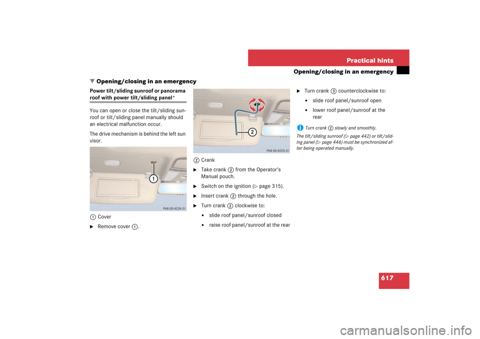
Remove cover1.2Crank
�
Take crank2 from the Operator’s
Manual pouch.
�
Switch on the ignition (
�page 315).
�
Insert crank2 through the hole.
�
Turn crank2 clockwise to:�
slide roof panel/sunroof closed
�
raise roof panel/sunroof at the rear
�
Turn crank3 counterclockwise to:�
slide roof panel/sunroof open
�
lower roof panel/sunroof at the
rear
i
Turn crank2 slowly and smoothly.
The tilt/sliding sunroof (
�page 442) or tilt/slid-
ing panel (
�page 446) must be synchronized af-
ter being operated manually.

Replacing SmartKey bat")