Page 505 of 570
504 Practical hints
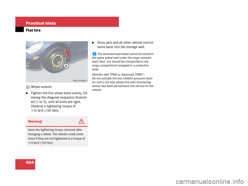
Flat tire
6Wheel wrench
�Tighten the five wheel bolts evenly, fol-
lowing the diagonal sequence illustrat-
ed (1 to 5), until all bolts are tight.
Observe a tightening torque of
110 lb-ft (150 Nm).
�Store jack and all other vehicle tool kit
items back into the storage well.
Warning!G
Have the tightening torque checked after
changing a wheel. The wheels could come
loose if they are not tightened to a torque of
110 lb-ft (150 Nm).
iThe removed road wheel cannot be stored in
the spare wheel well under the cargo compart-
ment floor, but should be transported in the
cargo compartment wrapped in a protective
wrap.
Vehicles with TPMS or Advanced TPMS*:
Do not activate the tire inflation pressure moni-
tor until a full size wheel/tire with functioning
sensor has been placed back into service on the
vehicle.
Page 518 of 570

517 Practical hints
Towing the vehicle
�Towing the vehicle
Mercedes-Benz recommends that the
vehicle be transported with all wheels off
the ground using flatbed or appropriate
wheel lift/dolly equipment. This method is
preferable to other types of towing.When circumstances do not permit the
recommended towing methods, the
vehicle may be towed with all wheels on
the ground only so far as necessary to have
the vehicle moved to a safe location where
the recommended towing methods can be
employed.
!Use flatbed or wheel lift/dolly equipment,
with the SmartKey in starter switch turned to
position0.
Do not tow with sling-type equipment. Towing
with sling-type equipment over bumpy roads will
damage radiator and supports.
To prevent damage during transport, do not tie
down vehicle by its chassis or suspension parts.
Use the towing eyes.
Switch off the ESP
® (�page 104) and the
automatic central locking (
�page 130).
!Do not tow-start the vehicle.
!Do not tow with one axle raised. Doing so
could damage the transfer case, which is not
covered by the Mercedes-Benz Limited
Warranty.
All wheels must be on or off the ground. Observe
instructions for towing the vehicles with all
wheels on the ground.
Warning!G
If circumstances require towing the vehicle
with all wheels on the ground, always tow
with a tow bar if:
�the engine will not run
�there is a malfunction in the power
supply or in the vehicle’s electrical
system
Prior to towing the vehicle with all wheels on
the ground, make sure the starter switch is
in position2 (
�page 39).
Warning!G
With the engine not running, there is no
power assistance for the brake and steering
systems. In this case, it is important to keep
in mind that a considerably higher degree of
effort is necessary to brake and steer the
vehicle. Adapt your driving accordingly.
!When towing the vehicle with all wheels on
the ground, the automatic transmission must be
in positionN and the starter switch must be in
position2 (
�page 39).
When towing the vehicle with all wheels on the
ground, the vehicle may be towed only for
distances up to 30 miles (50 km) and at a speed
not to exceed 30 mph (50 km / h).
Keep in mind that it is important for the
SmartKey to be in the respective starter switch
positions as described above. As soon as the
SmartKey is removed from the starter switch or
the SmartKey with KEYLESS-GO* is removed
from the vehicle, the automatic transmission will
shift to park positionP, see “Starter switch posi-
tions” (
�page 39).
Page 519 of 570

518 Practical hints
Towing the vehicle
Installing towing eye bolt
Depending on whether you are towing a
vehicle or you are being towed, the towing
eye bolt can be screwed into threaded
holes which are located behind covers on
the right-hand side of each bumper.
Example illustration R 500
1Towing eye cover
Example illustration R 500
1Towing eye cover
!Towing of the vehicle should only be done
using the towing eye. Never attach tow cable,
tow rope or tow rod to vehicle chassis, frame or
suspension parts.
iWhen towing the vehicle with all wheels on
the ground, note the following:
With the automatic central locking activated and
the ignition in position2 (
�page 39), the vehicle
doors lock if the left front wheel is turning at a
speed of approx. 9 mph (15 km / h) or above.
To prevent the vehicle doors from locking,
deactivate the automatic central locking
(
�page 130).
iTo signal turns while being towed with
hazard warning flasher in use, set the starter
switch to position2 and activate combination
switch for left or right turn signal in usual manner
– only the selected turn signal will operate.
Upon canceling the turn signal, the hazard warn-
ing flasher will operate again.
iIf the battery is disconnected or discharged,
the automatic transmission will remain locked in
positionP and the SmartKey will not turn in the
starter switch. For more information, see “Bat-
tery” (
�page 506) and “Jump starting”
(
�page 514).
Warning!G
In order to avoid possible serious burns or
injury, use extreme caution when removing
the cover, because the rear exhaust pipe is
extremely hot.
Page 520 of 570

519 Practical hints
Towing the vehicle
Removing cover
�Press mark on cover1 as indicated by
the arrow.
�Lift off cover1 to reveal the threaded
hole for towing eye bolt.
Installing towing eye bolt
�Take the towing eye bolt and wheel
wrench from the vehicle toolkit
(
�page 473).
�Screw towing eye bolt in to its stop and
tighten with wheel wrench.Removing towing eye bolt
�Loosen towing eye bolt counterclock-
wise with wheel wrench.
�Unscrew towing eye bolt.
�Store the towing eye bolt and wheel
wrench back into the vehicle toolkit
(
�page 473).
�Engage cover1 at top and press at
bottom.
Installing cover
�Engage cover1 at top and press at
bottom.
Stranded vehicle
Freeing a stranded vehicle, on which the
wheels are dug into sand or mud, should
be done with the greatest of care, espe-
cially if the vehicle is heavily loaded.
Avoid pulling the vehicle abruptly or diago-
nally, since it could result in damage to the
chassis alignment.
Never try to free a vehicle that is still cou-
pled to a trailer.
If possible, a vehicle equipped with trailer
hitch receiver should be pulled backward
in its own previously made tracks.
Page 522 of 570
521 Practical hints
Fuses
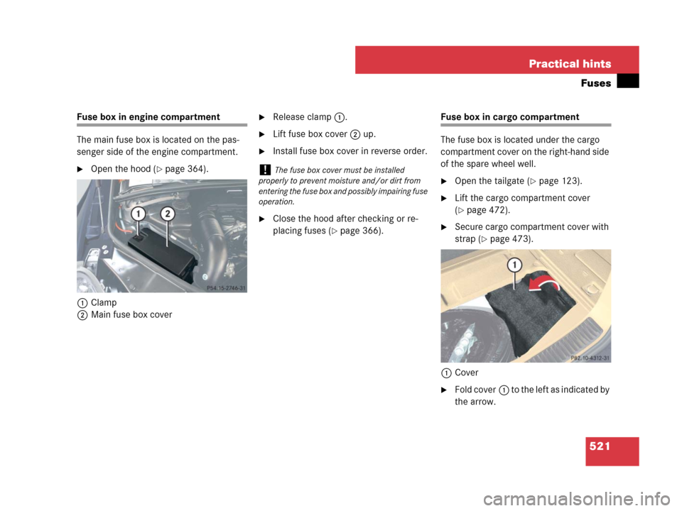
Fuse box in engine compartment
The main fuse box is located on the pas-
senger side of the engine compartment.
�Open the hood (�page 364).
1Clamp
2Main fuse box cover
�Release clamp1.
�Lift fuse box cover2 up.
�Install fuse box cover in reverse order.
�Close the hood after checking or re-
placing fuses (
�page 366).
Fuse box in cargo compartment
The fuse box is located under the cargo
compartment cover on the right-hand side
of the spare wheel well.
�Open the tailgate (�page 123).
�Lift the cargo compartment cover
(
�page 472).
�Secure cargo compartment cover with
strap (
�page 473).
1Cover
�Fold cover1 to the left as indicated by
the arrow.
!The fuse box cover must be installed
properly to prevent moisture and/or dirt from
entering the fuse box and possibly impairing fuse
operation.
Page 533 of 570

532 Technical data
Rims and tires
!Only use tires which have been tested and
approved by Mercedes-Benz. Tires approved by
Mercedes-Benz are developed to provide best
possible performance in conjunction with the
driving safety systems on your vehicle such as
ABS or ESP
®. Tires specially developed for your
vehicle and tested and approved by
Mercedes-Benz can be identified by finding the
following on the tire’s sidewall:
�MO = Mercedes-Benz Original equipment
tires
AMG vehicles:
Does not apply to all approved tires on AMG
vehicles. For information on tested and
approved tires for AMG vehicles, contact an
authorized Mercedes-Benz Center.
Using tires other than those approved by
Mercedes-Benz may result in damage that is
not covered by the Mercedes-Benz Limited
Warranty.
!Using tires other than those approved by
Mercedes-Benz can have detrimental effects,
such as
�poor handling characteristics
�increased noise
�increased fuel consumption
Moreover, tires and rims not approved by
Mercedes-Benz may, under load, exhibit dimen-
sional variations and different tire deformation
characteristics that could cause them to come
into contact with the vehicle body or axle parts.
Damage to the tires or the vehicle may be the
result.
iFurther information on tires and rims is
available at any authorized Mercedes-Benz Light
Truck Center. A placard with the recommended
tire inflation pressures is located on the driver’s
door B-pillar (
�page 376). Some vehicles may
have supplemental tire inflation pressure infor-
mation for driving at high speeds (
�page 381)
or for vehicle loads less than the maximum
loaded vehicle condition (
�page 382). If such
information is provided, it can be found on the
placard located on the inside of the fuel filler
flap.The tire inflation pressure should be checked
regularly and should only be adjusted on cold
tires. Follow tire manufacturer’s maintenance
recommendation included with vehicle.
iThe following pages also list the approved
wheel rim and tire sizes for equipping your vehi-
cles with winter tires. Winter tires are not avail-
able as standard or optional factory equipment,
but can be purchased from an authorized
Mercedes-Benz Light Truck Center.
Depending on vehicle model and the standard or
optional factory-equipped wheel rim/tire
configuration on your vehicle (Appearance
Package, Sport Package etc.), equipping your
vehicle with winter tires approved for your
vehicle model may also require the purchase of
two or four wheel rims of the recommended size
for use with these winter tires. See an authorized
Mercedes-Benz Light Truck Center for more
information.
Page 534 of 570
533 Technical data
Rims and tires
Same size tires
R320CDI
R350R500R320CDI (Sport Package*)
R 350 (Sport Package*)
R 500 (Sport Package*)
Rims (light alloy)7.5 J x 17 H28Jx18H28Jx19H2
Wheel offset2.20 in (56 mm)2.64 in (67 mm)2.64 in (67 mm)
All-season tires1235/65 R17 104H M+S255/55 R18 105H M+S255/50 R19 107H XL (Extra Load) M+S
Winter tires1,2235/65 R17 104H M+S.255/55 R18 105H M+S.255/50 R19 107H XL (Extra Load) M+S.
R320CDI (Sport Package*)
R 350 (Sport Package*)
R 500 (Sport Package*)R63AMG
AMG rims (light alloy)8.5Jx19H28.5Jx20H2
Wheel offset2.52 in (64 mm)2.36 in (60 mm)
All-season tires1255/50 R19 107H XL (Extra Load) M+S –
Summer tires1 –265/45 ZR20 104Y
Winter tires1,2255/50 R19 107H XL (Extra Load) M+S.255/45 R20 105V XL (Extra Load) M+S.
1Radial-ply tires2Not available as factory equipment.
Page 535 of 570
534 Technical data
Rims and tires
Spare wheel (collapsible tire)
R320CDI
R350
R500R63AMG
Rim (steel)6.5 B x 18 H2–
Rim (light alloy)–5.5 B x 19 H2
Wheel offset1.58 in (40 mm)0.51 in (13 mm)
Collapsible tire 1
1Must not be used with snow chains.
195/75-18 106P185/65-19 104P
Recommended tire inflation pressure44 psi (3.0 bar)51 psi (3.5 bar)
!Please compare the recommended tire
inflation pressure for your vehicle with the tire
inflation pressure on the yellow label located on
the spare wheel rim.
If the tire inflation pressure on the yellow label
on the spare wheel rim differs from the values
given in this Operator’s Manual, inflate the
collapsible tire to the recommended tire inflation
pressure given on the yellow label on the spare
wheel rim.iPlease note that the tire inflation pressure of
the collapsible tire differs from the tire inflation
pressure of the road tires.

R 350 (Sport Package*)
R 500 (Sport Package*)
Rims (light alloy)7.5 J x 17 H28Jx18H28Jx19H2
Wheel offset2.20")

R320CDI
R350
R500R63AMG
Rim (steel)6.5 B x 18 H2–
Rim (light alloy)–5.5 B x 19 H2
Wheel offset1.58 in (40 mm)0.51 in (13 mm)
Collap")