Page 65 of 386

64
fig. 47
L0A0310b
Recalling the “parking” position
of the external rear view mirror
on passenger side
To automatically recall the “park-
ing” position of the external passen-
ger rear view mirror, proceed as fol-
lows:
– with the car stopped and the igni-
tion key at MAR, engage the reverse
gear; the mirror will be automatical-
ly brought back to the previously
stored position .
If no “parking” position has been
stored, when engaging reverse the
passenger mirror slightly lowers
than normally to a preset position to
facilitate the driver during parking.
The rear view mirror will automat-
ically return to its initial position
after about 10 seconds from reverse
gear disengagement, or immediately
after exceeding a speed of 10 km/h
with forward gear. IMPORTANTThe “parking” posi-
tion memorisation and recall can
only be performed with ignition key
at MAR.
Automatic realignment
of external rear view mirrors
Every time the ignition key is
turned to MAR, the external rear
view mirrors automatically return to
the latest position reached and/or
recalled before removing the key.
This enables rear view mirror
alignment if, when the car is parked,
one of the rear view mirror has been
manually and/or accidentally
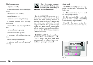
moved.COMFORT SEATS (fig. 47)
Button Aon front Comfort Seats
enables to actuate the respective con-
trols separately. When pressing the
button of each of the two seats, the
respective CONNECT menu is actu-
ated; this menu makes it possible,
through its various options, to define
the heating levels and actuate venti-
lation, massage and the adaptive
function for each of the two seats.
The Comfort controls can also be
actuated by pressing the “Setup” key
of the CONNECT and then selecting
the “Seat Comfort” function.
To actuate these settings, refer to
the CONNECT supplement provid-
ed with the car.
IMPORTANTNever turn the pas-
senger massage function on when
the seat is not occupied since the
occupant sensor could activate (in
the event of an accident) the rele-
vant air bag.
Page 66 of 386

65
Remember that the head
restraints should be
adjusted to support the
back of your head and not your
neck. Only if they are in this posi-
tion will they be able to provide
effective protection in the event of
a rear-end shunt. Never drive
your car without fitting the head-
rest: this is dangerous and, more-
over, is prohibited by the law.ARMREST (fig. 49)
The armrest Acan be adjusted up
or down to three different positions.
To lift the armrest, pull it from
handgrip B. To lower the armrest,
keep knob Cdepressed.
The armrest incorporates a cli-
mate-controlled bottle/can holder
(refer to the relevant paragraph in
this chapter). To gain access to the
bottle/can holder, lift armrest Aby
pulling it from handgrip B. To close
the bottle/can holder, lower the
armrest until it is locked; to lower it
further, press knob C.HEAD RESTRAINTS (fig. 48)
Where provided, front head
restraints can be adjusted electrical-
ly, so as to adapt to the driver’s
height.
To lift the head restraint, move
control B(fig. 43) to 7; to lower the
head restraint, move the aforesaid
control to 8.
To remove the head restraints,
move them upwards, to refit them,
fit the rods back into the housings
on the seat top.
fig. 48
L0A0148b
fig. 49
L0A0169b
Page 67 of 386
66
REAR SEATS
HEAD RESTRAINTS
The 3 rear head restraints (fig. 50-
51) can be adjusted for height. To
adjust, move the head restraint
upwards or downwards according to
the most suitable position.
Rear head restraints cannot be
removed.Remember that the head
restraints should be
adjusted to support the
back of your head and not your
neck. Only if they are in this posi-
tion will they be able to provide
effective protection in the event of
a rear-end shunt. Certain versions (where provided)
have a button A(fig. 52) on the cen-
tral console for lowering, with igni-
tion key at MAR, the rear side head
restraints.
fig. 50
L0A0166b
fig. 51
L0A0165b
fig. 52
L0A0168b
Page 68 of 386

67
ARMREST
Lower the armrest to the position
shown for use by pulling the lever A
(fig. 53).
To close, lift the armrest into its
housing.
An oddment compartment is con-
cealed inside the armrest and
according to versions it can contain
the following:
– buttons for heating control, mas-
sage, lumbar adjustment and rear
side seat adaptive function
– button for moving the front pas-
senger seat– button for opening/closing the
electric sunshade
– current socket
– remote control for CONNECT
HI-FI and TV functions.
IMPORTANTRead through the
instruction given in paragraph
“Interior equipment” in this chapter
for current socket use.
To open the oddment compart-
ment, lift the armrest cover using
grip A(fig. 54). To close the odd-
ment compartment lower the cover. HEATING (fig. 55)
To switch side seat heating on, turn
knob A(left-hand seat) or B(right-
hand seat) to “1”, “2” or “3” that
correspond to the different warming
levels. To switch seat heating off,
turn the knob to “0”.
fig. 53
L0A0076b
fig. 54
L0A0074b
fig. 55
L0A0102b
Page 69 of 386

68
COMFORT SEATS
Side Comfort seats are fitted with
independent control buttons for
heating, lumbar adjustment, mas-
sage and adjusting function; these
controls are located inside the arm-
rest.
The armrest compartment houses
also the button for moving the front
passenger seat and the button con-
trolling the electric sunshade.
Controls are operative in one of the
following conditions:
– ignition switch to MAR
– for approx. 1 minute after
removing the ignition key or turning
it to STOP– for approx. 3 minutes with key
removed or turned to STOPand
with door open.
Armrest compartment control but-
ton layout is as follows (fig. 56):
A– Buttons for lumbar adjustment,
massage and right-hand seat adap-
tive function
B– Button for right-hand seat
heating
C– Buttons for lumbar adjustment,
massage and left-hand seat adaptive
function
D– Button for left-hand seat heat-
ing
E– Button for moving front pas-
senger’s seatF– Electric sunshade control but-
ton.
IMPORTANTTo allow system
automatic configuration, press the
buttons for about 2 seconds to acti-
vate the required function.
Right-hand seat adjustment
(fig. 57)
1 – Lumbar support increase
2– Lumbar support decrease
3– Massage activation
4– Massage deactivation
5– Adaptive function on
6– Adaptive function off
This device makes it possible to
vary back support and improve
comfort. Press button 1to increase
the support and button 2to decrease
it.
The massage function reduces the
stress specially during long journeys.
Press button 3to start the massage
and button 4to stop it.
fig. 56
L0A0312b
fig. 57
L0A0311b
Page 70 of 386

69
The adaptive function makes it
possible to adapt the seat back to the
passenger thus improving comfort
and back support. Press button 5to
activate this function and button 6
to deactivate it.
Right-hand seat heating – Button
B (fig. 56)
To switch seat heating on, turn
knob to “1”, “2” or “3” that corre-
spond to the different warming lev-
els. To switch seat heating off, turn
the knob to “0”.Left-hand seat adjustment
(fig. 57)
7– Lumbar support increase
8– Lumbar support decrease
9 – Massage activation
10– Massage deactivation
11– Adaptive function on
12– Adaptive function off
This device makes it possible to
vary back support and improve
comfort. Press button 7to increase
the support and button 8to decrease
it.
The massage function reduces the
stress specially during long journeys.
Press button 9to start the massage
and button 10to stop it.
The adaptive function makes it
possible to adapt the seat back to the
passenger thus improving comfort
and back support. Press button 11
to activate this function and button
12to deactivate it.Left-hand seat heating
Button D (fig. 56)
To switch seat heating on, turn
knob to “1”, “2” or “3” that corre-
spond to the different warming lev-
els. To switch seat heating off, turn
the knob to “0”.
Moving the front passenger’s seat
backwards or forwards – Button E
(fig. 56)
Press the front part of the button to
move the front passenger’s seat for-
ward and increase the space available
for the rear passenger. Press the rear
part of the button to move the seat
backwards.
Electric sunshade -
Button F (fig. 56)
Press the front part of the button to
open the sunshade and the rear part
to close it (see paragraph “Electric
sunshade” in this chapter).
Page 71 of 386

It is absolutely forbidden
to carry out whatever af-
ter-market operation in-
volving steering system or steering
column modifications (e.g.: instal-
lation of anti-theft Device) that
could badly affect performance
and safety, cause the lapse of war-
ranty and also result in non-com-
pliance of the car with homologa-
tion requirements.
70
STEERING WHEELSteering wheel position is stored
together with external rearview mir-
ror position, when storing the dri-
ver’s seat position.
MANUAL ADJUSTMENT (fig. 59)
The steering wheel height and axial
position can be adjusted:
On certain versions the steering
wheel height and axial position can be
adjusted; proceed as follows:
1) Push lever Bto 1.
2) Move the steering wheel to the re-
quired position by pulling, pushing,
lifting or lowering it.
3) Pull leverBto 2to lock the steer-
ing wheel in place. Only make adjustments
when the car is station-
ary.
ELECTRIC ADJUSTMENT
(fig. 58)
The steering wheel height and axial
position can be adjusted electroni-
cally when the ignition key is at
MAR.
To make adjustments, move lever
Ain four directions.
fig. 58
L0A0104b
fig. 59
L0A0000b
Page 72 of 386
71
Automatically adjustable (fig. 61)
The mirror is automatically set to
day and night position, irrespective-
ly of exterior lights.
The mirror sets always in day posi-
tion when engage the reverse gear.EXTERNAL REARVIEW
MIRRORS
External rearview mirrors have flat
surface and can be heated and
adjusted automatically when the
ignition key is at MAR.
Turn switch A(fig. 62) to position
1(left-hand mirror) or to position 2
(right-hand mirror) to select the
mirror to be adjusted.
fig. 61
L0A0247b
fig. 62
L0A0085b
REARVIEW
MIRRORS
INTERNAL REARVIEW MIRROR
Manually adjustable (fig. 60)
The mirror can be adjusted in four
directions by means of lever A:
1) normal position
2) anti-dazzle position.
The mirror is also fitted with a
safety device that releases the mirror
in the event of an impact.
fig. 60
L0A0269b