Page 833 of 1575
2007 > 2.7L V6 GASOLINE >
DESCRIPTION
Driver Airbag (DAB) is installed in steering wheel and electrically connected to SRSCM via clockspring. It protects the
driver from danger by deploying a bag when frontal crash occurs. The SRSCM determines deployment of Driver Airbag
(DAB).
Never attempt to measure the circuit resistance of the airbag module (squib) even if you are using the specified
tester. If the circuit resistance is measured with a tester, accidental airbag deployment will result in serious
personal injury.
Page 835 of 1575
2007 > 2.7L V6 GASOLINE >
REMOVAL
1.Disconnect the battery negative cable and wait at least three minutes before beginning work.
2. Remove the airbag module mounting bolts.
3.Disconnect the horn connector(A).
4.Release the connector locking pin(B), then disconnect the driver airbag module connector(C).
The removed airbag module should be stored in a clean, dry place with the pad cover face up.
5. Remove the steering wheel and steering wheel column cover(Refer to ST group in the Workshop Manual).
6. Disconnect the clock spring and horn connector, then remove the clock spring.
INSTALLATION
1.Disconnect the negative ( - ) cable from battery and wait for at least three minutes.
Page 836 of 1575

2.Remove ignition key from the vehicle.
3. Connect the clock spring harness connetor and horn harness connector to the clock spring.
4. Set the clock spring on neutral position and after turning the front wheels to the straight- ahead position, install the
clock spring.
5. Install the steering wheel column cover and the steering wheel. (Refer to ST group)
6. Connect the Driver Airbag (DAB) module connector and horn connector, then install the Driver Airbag (DAB)
module on the steering wheel.
7. Secure the Driver Airbag (DAB) with the new mounting bolts.
Tightening Torque (DAB Mounting Bolt)
: 0.8 ~ 1.1 kgf.m (7.9 ~ 10.8 Nm, 5.8 ~ 8.0 lb.ft)
8.Connect the battery negative cable.
9. After installing the airbag, confirm proper system operation:
a. Turn the ignition switch ON; the SRS indicator light should be turned on for about six seconds and then go off.
b. Make sure horn button works.
INSPECTION
Driver Airbag (DAB)
If any improper parts are found during the following inspection, replace the airbag module with a new one.
Never attempt to measure the circuit resistance of the airbag module (squib) even if you are using the specified
tester. If the circuit resistance is measured with a tester, accidental airbag deployment will result in serious
personal injury.
1. Check pad cover for dents, cracks or deformities.
2. Check the airbag module for denting, cracking or deformation.
3. Check hooks and connectors for damage, terminals for deformities, and harness for binds.
Page 837 of 1575
4.Check airbag inflator case for dents, cracks or deformities.
5.Install the airbag module to the steering wheel to check for fit or alignment with the wheel.
Clockspring
1.If, as a result of the following checks, even one abnormal point is discovered, replace the clock spring with a new
one.
2. Check connectors and protective tube for damage, and terminals for deformities.
Page 853 of 1575
2007 > 2.7L V6 GASOLINE >
DESCRIPTION
The Seat Belt Pretensioners (BPT) are installed inside Center Pillar (LH & RH). When a vehicle crashes with a certain
degree of frontal impact, the pretensioner seat belt helps to reduce the severity of injury to the front seat occupants by
retracting the seat belt webbing. This prevents the front occupants from thrusting forward and hitting the steering
wheel or the instrument panel when the vehicle crashes.
Never attempt to measure the circuit resistance of the Seat Belt Pretensioner (BPT) even if you are using the
specified tester. If the circuit resistance is measured with a tester, the pretensioner will be ignited accidentally.
This will result in serious personal injury.
Page 857 of 1575
2007 > 2.7L V6 GASOLINE >
DESCRIPTION
The Seat Belt Buckle Pretensioners (BUPT) are installed in the right side of the driver seat and the left side of the
passenger seat. When a vehicle crashes with a certain degree of frontal impact, the seat belt buckle pretensioner
helps to reduce the severity of injury to the front seat occupants by retracting the seat belt buckle. This prevents the
front occupants from thrusting forward and hitting the steering wheel or the instrument panel when the vehicle crashes.
Never attempt to measure the circuit resistance of the Seat Belt Buckle Pretensioner (BUPT) even if you are
using the specified tester. If the circuit resistance is measured with a tester, the pretensioner will be ignited
accidentally. This will result in serious personal injury.
Page 867 of 1575

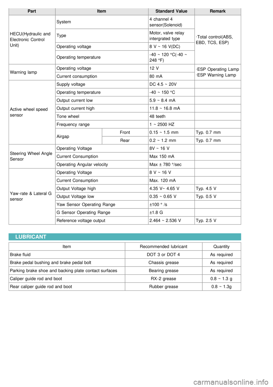
PartItemStandard ValueRemark
HECU(Hydraulic and
Electronic Control
Unit) System
4 channel 4
sensor(Solenoid)
·Total control(ABS,
EBD, TCS, ESP)
Type
Motor, valve relay
intergrated type
Operating voltage 8 V ~ 16 V(DC)
Operating temperature - 40 ~ 120 °C(- 40 ~
248 °F)
Warning lamp Operating voltage
12 V
·ESP Operating Lamp
·ESP Warning Lamp
Current consumption 80 mA
Active wheel speed
sensor Supply voltage
DC 4.5 ~ 20V
Operating temperature - 40 ~ 150 °C
Output current low 5.9 ~ 8.4 mA
Output current high 11.8 ~ 16.8 mA
Tone wheel 48 teeth
Frequency range 1 ~ 2500 HZ
Airgap Front
0.15 ~ 1.5 mm Typ. 0.7 mm
Rear 0.2 ~ 1.2 mm Typ. 0.7 mm
Steering Wheel Angle
Sensor Operating Voltage
8V ~ 16 V
Current Consumption Max 150 mA
Operating Angular velocity Max ± 780 °/sec
Yaw - rate & Lateral G
sensor Operating Voltage
8 V ~ 16 V
Current Consumption Max. 120 mA
Output Voltage high 4.35 V~ 4.65 VTyp. 4.5 V
Output Voltage low 0.35 ~ 0.65 VTyp. 0.5 V
Yaw Sensor Operating Range ±100 ° /s
G Sensor Operating Range ±1.8 G
Reference voltage output 2.464 ~ 2.536 VTyp. 2.5 V
LUBRICANT
Item Recommended lubricantQuantity
Brake fluid DOT 3 or DOT 4As required
Brake pedal bushing and brake pedal bolt Chassis greaseAs required
Parking brake shoe and backing plate contact surfaces Bearing greaseAs required
Caliper guide rod and boot RX - 2 grease0.8 ~ 1.3 g
Rear caliper guide rod and boot Rubber grease0.8 ~ 1.3g
Page 928 of 1575

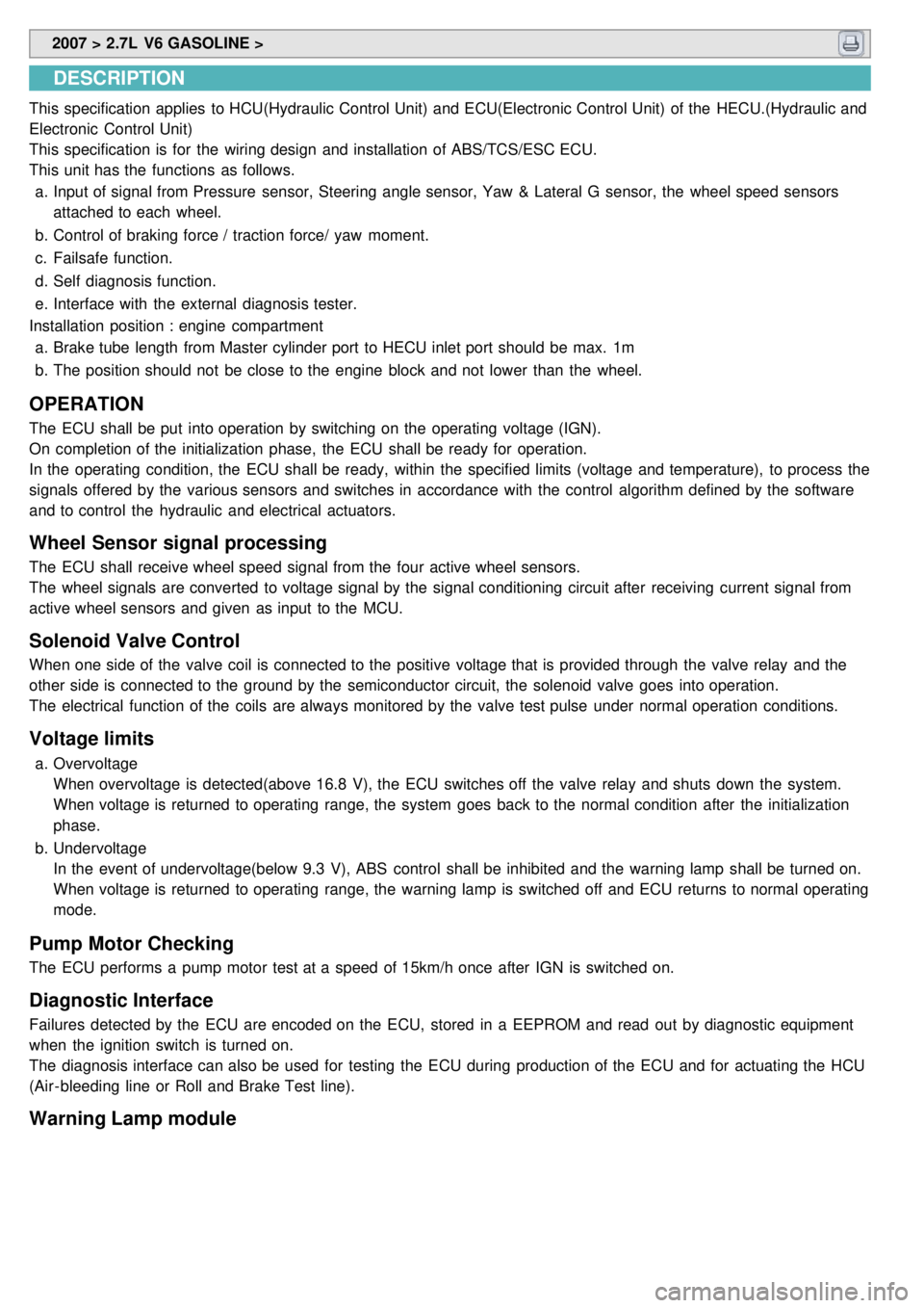
2007 > 2.7L V6 GASOLINE >
DESCRIPTION
This specification applies to HCU(Hydraulic Control Unit) and ECU(Electronic Control Unit) of the HECU.(Hydraulic and
Electronic Control Unit)
This specification is for the wiring design and installation of ABS/TCS/ESC ECU.
This unit has the functions as follows.
a. Input of signal from Pressure sensor, Steering angle sensor, Yaw & Lateral G sensor, the wheel speed sensors
attached to each wheel.
b. Control of braking force / traction force/ yaw moment.
c. Failsafe function.
d. Self diagnosis function.
e. Interface with the external diagnosis tester.
Installation position : engine compartment a. Brake tube length from Master cylinder port to HECU inlet port should be max. 1m
b. The position should not be close to the engine block and not lower than the wheel.
OPERATION
The ECU shall be put into operation by switching on the operating voltage (IGN).
On completion of the initialization phase, the ECU shall be ready for operation.
In the operating condition, the ECU shall be ready, within the specified limits (voltage and temperature), to process the
signals offered by the various sensors and switches in accordance with the control algorithm defined by the software
and to control the hydraulic and electrical actuators.
Wheel Sensor signal processing
The ECU shall receive wheel speed signal from the four active wheel sensors.
The wheel signals are converted to voltage signal by the signal conditioning circuit after receiving current signal from
active wheel sensors and given as input to the MCU.
Solenoid Valve Control
When one side of the valve coil is connected to the positive voltage that is provided through the valve relay and the
other side is connected to the ground by the semiconductor circuit, the solenoid valve goes into operation.
The electrical function of the coils are always monitored by the valve test pulse under normal operation conditions.
Voltage limits
a.Overvoltage
When overvoltage is detected(above 16.8 V), the ECU switches off the valve relay and shuts down the system.
When voltage is returned to operating range, the system goes back to the normal condition after the initialization
phase.
b. Undervoltage
In the event of undervoltage(below 9.3 V), ABS control shall be inhibited and the warning lamp shall be turned on.
When voltage is returned to operating range, the warning lamp is switched off and ECU returns to normal operating
mode.
Pump Motor Checking
The ECU performs a pump motor test at a speed of 15km/h once after IGN is switched on.
Diagnostic Interface
Failures detected by the ECU are encoded on the ECU, stored in a EEPROM and read out by diagnostic equipment
when the ignition switch is turned on.
The diagnosis interface can also be used for testing the ECU during production of the ECU and for actuating the HCU
(Air - bleeding line or Roll and Brake Test line).
Warning Lamp module