Page 603 of 1575
14.Remove the power steering gear box (A) from the sub- frame by loosening the mounting bolts.
Tightening torque Nm (kgf.m, lb - ft):
60 ~ 80 (6.0 ~ 8.0, 43~58)
INSTALLATION
Be sure to connect between a tube and a hose as shown in the illustration.
1.Installation is the reverse of removal.
2. After installation, bleed the power steering system. (Refer to the air bleeding in ST group)
3. Adjust the wheel alignment. (Refer to SS group)
DISASSEMBLY
1.Remove the tie rod end (B) from the tie rod (A).
Page 835 of 1575
2007 > 2.7L V6 GASOLINE >
REMOVAL
1.Disconnect the battery negative cable and wait at least three minutes before beginning work.
2. Remove the airbag module mounting bolts.
3.Disconnect the horn connector(A).
4.Release the connector locking pin(B), then disconnect the driver airbag module connector(C).
The removed airbag module should be stored in a clean, dry place with the pad cover face up.
5. Remove the steering wheel and steering wheel column cover(Refer to ST group in the Workshop Manual).
6. Disconnect the clock spring and horn connector, then remove the clock spring.
INSTALLATION
1.Disconnect the negative ( - ) cable from battery and wait for at least three minutes.
Page 836 of 1575

2.Remove ignition key from the vehicle.
3. Connect the clock spring harness connetor and horn harness connector to the clock spring.
4. Set the clock spring on neutral position and after turning the front wheels to the straight- ahead position, install the
clock spring.
5. Install the steering wheel column cover and the steering wheel. (Refer to ST group)
6. Connect the Driver Airbag (DAB) module connector and horn connector, then install the Driver Airbag (DAB)
module on the steering wheel.
7. Secure the Driver Airbag (DAB) with the new mounting bolts.
Tightening Torque (DAB Mounting Bolt)
: 0.8 ~ 1.1 kgf.m (7.9 ~ 10.8 Nm, 5.8 ~ 8.0 lb.ft)
8.Connect the battery negative cable.
9. After installing the airbag, confirm proper system operation:
a. Turn the ignition switch ON; the SRS indicator light should be turned on for about six seconds and then go off.
b. Make sure horn button works.
INSPECTION
Driver Airbag (DAB)
If any improper parts are found during the following inspection, replace the airbag module with a new one.
Never attempt to measure the circuit resistance of the airbag module (squib) even if you are using the specified
tester. If the circuit resistance is measured with a tester, accidental airbag deployment will result in serious
personal injury.
1. Check pad cover for dents, cracks or deformities.
2. Check the airbag module for denting, cracking or deformation.
3. Check hooks and connectors for damage, terminals for deformities, and harness for binds.
Page 916 of 1575
11.Remove the four mounting bolts (A) of the parking brake wire bracket from the rear cross member.
12.Remove the rear wheels and tires from the rear hubs.
13. Remove the hub cap (A) and the disc (B).
14.Remove the hub nut (A) and washer (B) and remove the rear hub (C).
15.Remove the shoe hold down pin and spring (A) by pressing and rotating the spring.
Page 1566 of 1575

2007 > 2.7L V6 GASOLINE >
REPLACEMENT
1.Remove a transaxle assembly (refer to 'MT'- group).
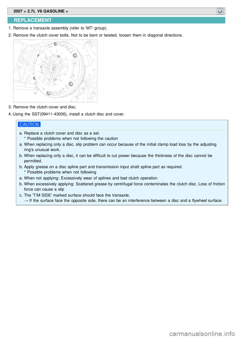
2. Remove the clutch cover bolts. Not to be bent or twisted, loosen them in diagonal directions.
3.Remove the clutch cover and disc.
4. Using the SST(09411- 43000), install a clutch disc and cover.
a. Replace a clutch cover and disc as a set.
* Possible problems when not following the caution
a. When replacing only a disc, slip problem can occur because of the initial clamp load loss by the adjusting
ring's unusual work.
b. When replacing only a disc, it can be difficult to cut power because the thickness of the disc cannot be
permitted.
b. Apply grease on a disc spline part and transmission input shaft spline part as required.
* Possible problems when not following
a. When not applying: Excessively wear of splines and bad clutch operation
b. When excessively applying: Scattered grease by centrifugal force conteminates the clutch disc. Loss of friction
force can cause a slip
c. The 'T/M SIDE' marked surface should face the transaxle.
→ If the surface face the opposite side, there can be an interference between a disc and a flywheel surface.